
Parallel IGBT module copper bar installation structure

An installation structure and parallel technology, applied in the direction of output power conversion devices, electrical components, etc., can solve the problems of inconvenient installation, uncompact structure, module damage, etc., and achieve the effect of easy installation, compact structure and good current sharing effect

Inactive Publication Date: 2010-06-23
SUNGROW POWER SUPPLY CO LTD
View PDF0 Cites 4 Cited by
  • Summary
  • Abstract
  • Description
  • Claims
  • Application Information

AI Technical Summary

Problems solved by technology

The usual practice is to use a single copper bar or cable to connect each output stage of the module, which is difficult to ensure the current sharing of each module, and it is easy to cause damage to the module that bears a large current; it is also inconvenient to install and the structure is not compact

Method used


Image

  • Parallel IGBT module copper bar installation structure
  • Parallel IGBT module copper bar installation structure
  • Parallel IGBT module copper bar installation structure

Examples


Embodiment 1

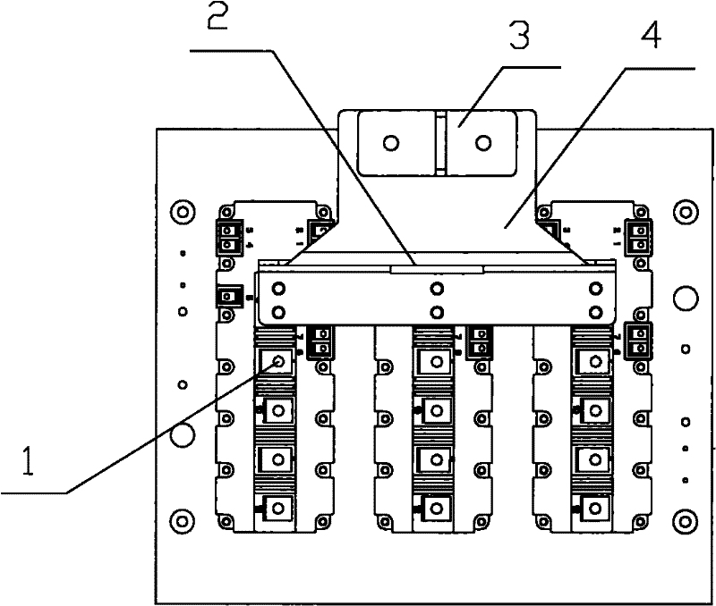
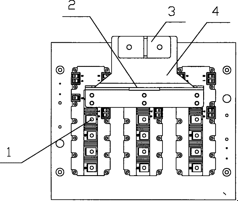
[0014] See attached figure 1 shown.

[0015] The transfer copper bar 3 is centrally and fixedly installed on the upper part of the short-circuit copper bar 4 , and the three IGBT modules 1 are installed on the lower part of the short-circuit copper bar 4 through the mounting holes provided on the short-circuit copper bar 4 . Between the transfer copper bar 3 and the installation position of the IGBT module 1 on the short-circuit copper bar 4, a current-blocking slot 2 is opened on the body of the short-circuit copper bar 4, and the current-blocking slot 2 is centered On the short-circuit copper bar 4. The three IGBT modules 1 are connected to the short-circuit copper bar 4 , so that the current flowing through each IGBT module 1 is basically the same, and evenly flows to the transfer copper bar 3 through the short-circuit copper bar 4 . The short-circuit copper bar 4 is provided with a long slot hole 2 for blocking current on the substrate, which changes the current path and...

Embodiment 2

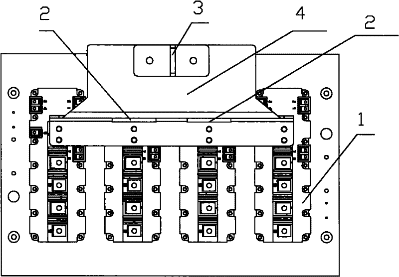
[0017] See attached figure 2 shown.

[0018] The transfer copper bar 3 is centrally and fixedly installed on the upper part of the short-circuit copper bar 4 , and the four IGBT modules 1 are installed on the lower part of the short-circuit copper bar 4 through the mounting holes provided on the short-circuit copper bar 4 . Between the transfer copper bar 3 and the installation position of the IGBT module 1 on the short-circuit copper bar 4, there are two current-blocking slots 2 on the body of the short-circuit copper bar 4, and the current-blocking slot 2 is centered Open on the short-circuit copper bar 4. The four IGBT modules 1 are connected to the short-circuit copper bar 4 , so that the current flowing through each IGBT module 1 is substantially the same, and evenly converged to the transfer copper bar 3 through the short-circuit copper bar 4 . The short-circuit copper bar 4 has two long slots 2 for blocking current on the substrate, changing the current path and achi...


PUM


Abstract

The invention relates to a parallel IGBT module copper bus bar installation structure. The copper bars comprises a short-connected copper bar and a switched copper bar, wherein the switched copper bar is fixedly arranged on the short-connected copper bar; at least one IGBT module is arranged on the short-connected copper bar; and a slotted hole is formed on a short-connected copper bar and between the installation positions of the switched copper bar and the IGBT module on the short-connected copper bar. The parallel IGBT module copper bar installation structure can well solve the problem of uniform flow of each IGBT module and is compact and simple.

Description

technical field [0001] The invention relates to a power supply module installation structure, in particular to an IGBT module installation structure. Background technique [0002] In the power electronics industry, due to the limited power that each IGBT module can withstand, it is often necessary to use multiple modules in parallel to increase the power capacity. The technical focus of parallel connection of multiple modules is to solve the current sharing of each module, which has great technical requirements and process difficulties. The usual practice is to use a single copper bar or cable to connect each output stage of the module, which is difficult to ensure the current sharing of each module, and it is easy to cause damage to the module that bears a large current; it is also inconvenient to install and the structure is not compact. Contents of the invention [0003] Aiming at the deficiencies of the prior art, the present invention designs and develops a compact a...

Claims


Application Information

Patent Timeline
Patent Type & Authority Applications(China)
IPC IPC(8): H02M1/00
Inventor 曹仁贤陶高周罗宣国李国宏李永红
Owner SUNGROW POWER SUPPLY CO LTD
Learn More