A current-limiting high-voltage DC circuit breaker

A high-voltage DC circuit breaker technology, which is applied in the direction of circuit devices, emergency protection circuit devices, emergency protection devices for automatic disconnection, etc., can solve the difficulties in the realization of DC circuit breakers, the inability to extinguish the arc at zero crossing point, and increase the shutdown delay, etc. problems, to achieve the effect of avoiding overcurrent of power electronic devices, avoiding waiting time, and improving shutdown current

Active Publication Date: 2019-05-31
NORTH CHINA ELECTRIC POWER UNIV (BAODING)
View PDF5 Cites 0 Cited by
  • Summary
  • Abstract
  • Description
  • Claims
  • Application Information

AI Technical Summary

Problems solved by technology

[0002] Due to many advantages, high-voltage and ultra-high-voltage direct current transmission have received more and more attention. In the future, multi-terminal direct current transmission and the direct current grid constructed from this will become a trend. However, the current of high-voltage direct current transmission has no zero crossing point and cannot be used like AC transmission. The use of zero-crossing point arc extinguishing brings great difficulties to the realization of DC circuit breakers. The current implementation methods are divided into the following types: based on superimposed oscillating current to generate current zero-crossing point, and then realize current breaking. The disadvantage is that the shutdown delay is too long. Long, the shutdown current is limited; the DC line adds an inverter-rectifier link, and the AC circuit breaker is used to cut off the current on the AC side after the inverter. The cost is expensive; a large number of power electronic devices are connected in series, and the arrester is connected in parallel on it. During normal operation, the current flows through the branch with lower impedance to reduce the loss. When it is turned off, the current is first transferred to the power electronic branch. Then turn on the isolating switch, turn it off with power electronic devices, and use lightning arresters to absorb fault energy
The disadvantage is that the shutdown current is limited, and the current needs to be transferred to the power electronic branch first, and the isolation switch must be fully opened, which increases the shutdown delay to a certain extent.

Method used


Image

  • A current-limiting high-voltage DC circuit breaker
  • A current-limiting high-voltage DC circuit breaker
  • A current-limiting high-voltage DC circuit breaker

Examples


Embodiment Construction

[0015] The technical solutions in the embodiments of the present application will be clearly and completely described below in conjunction with the drawings in the embodiments of the present application.

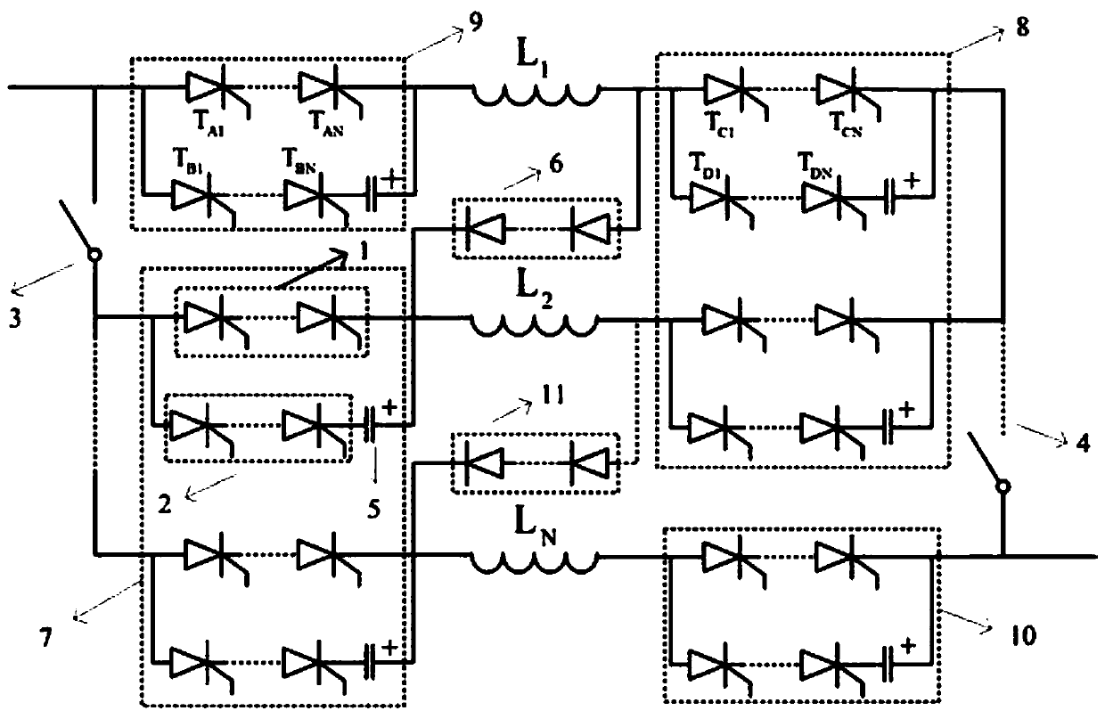
[0016] figure 1 Among the switch tubes in the dotted line boxes in 7, 8, 9, and 10, each branch includes two rows of switch tubes, and a capacitor is connected in series in the second row. The first row is represented by 1, and the second row is represented by 2, wherein the switch tubes in the dotted line boxes of 7 and 8 are operated when the current is limited, and the switch tubes in the dotted line boxes of 9 and 10 are operated when the circuit is off.

[0017] In the normal operation of the circuit, the isolating switches 3 and 4 are closed, and the thyristors (indicated by 1) in the first row of each branch in the dotted line boxes of 7, 8, 9, and 10 are in the on-state, and the thyristors in the second row (indicated by 1) are in the on-state. 2 means) is in the cu...


PUM


Abstract

The invention relates to a current-limiting high-voltage direct current breaker, and belongs to the technical field of high-voltage and extra-high-voltage direct current power transmission.The current-limiting high-voltage direct current breaker is composed of a certain number of branches and disconnecting switches; each branch is composed of a current-limiting inductor, a capacitor, a switching tube and a diode to have the effects of shunting and reducing loss.The current-limiting high-voltage direct current breaker is connected in a high-voltage direct current line in series, in normal operation, the inductors in all the branches are made to operate in parallel by means of control of a power electronic device, when the line or equipment breaks down, the current-limiting high-voltage direct current breaker does protective actions, the inductors connected in parallel are connected in series by means of control of the power electronic device, the disconnecting switches are turned on after the inductors are connected in series, then thyristors are controlled to conduct disconnection operation, and therefore the direct current equipment and the line are disconnected quickly.

Description

technical field [0001] The invention relates to a current-limiting high-voltage direct-current circuit breaker, which belongs to the field of high-voltage and extra-high-voltage direct-current transmission. Background technique [0002] Due to many advantages, high-voltage and ultra-high-voltage direct current transmission have received more and more attention. In the future, multi-terminal direct current transmission and the direct current grid constructed from this will become a trend. However, the current of high-voltage direct current transmission has no zero crossing point and cannot be used like AC transmission. The use of zero-crossing point arc extinguishing brings great difficulties to the realization of DC circuit breakers. The current implementation methods are divided into the following types: based on superimposed oscillating current to generate current zero-crossing point, and then realize current breaking. The disadvantage is that the shutdown delay is too long...

Claims


Application Information

Patent Timeline
Patent Type & Authority Patents(China)
IPC IPC(8): H02H3/087
CPCH02H3/087
Inventor 赵成勇李帅许建中郭春义
Owner NORTH CHINA ELECTRIC POWER UNIV (BAODING)
Why Eureka
Try Eureka