DC bus voltage following control circuit suitable for multi-path parallel LEDs

A technology of DC bus voltage and voltage control circuit, which is applied in the direction of electric lamp circuit arrangement, electric light source, lighting device, etc., can solve the problems of complex detection circuit, and achieve the effect of simplifying the control method

Active Publication Date: 2010-06-23
INVENTRONICS HANGZHOU
View PDF0 Cites 37 Cited by
  • Summary
  • Abstract
  • Description
  • Claims
  • Application Information

AI Technical Summary

Problems solved by technology

[0005] At the same time, if the voltage drop across the constant current control circuit is sampled and controlled, when the circuit is in the PWM dimming state, the voltage across the constant current control circuit is in a pulse state, and its detection circuit is complex

Method used


Image

  • DC bus voltage following control circuit suitable for multi-path parallel LEDs
  • DC bus voltage following control circuit suitable for multi-path parallel LEDs
  • DC bus voltage following control circuit suitable for multi-path parallel LEDs

Examples


Embodiment Construction

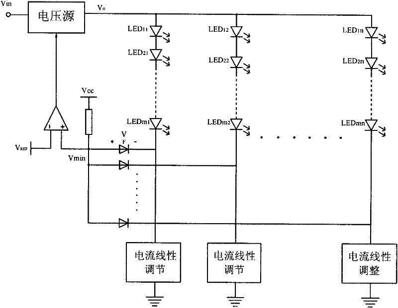
[0022] refer to figure 1 , in prior art 1, the minimum value of the voltage across the current linear regulation circuit is sampled, and a control signal is output to the voltage source to adjust the output voltage.

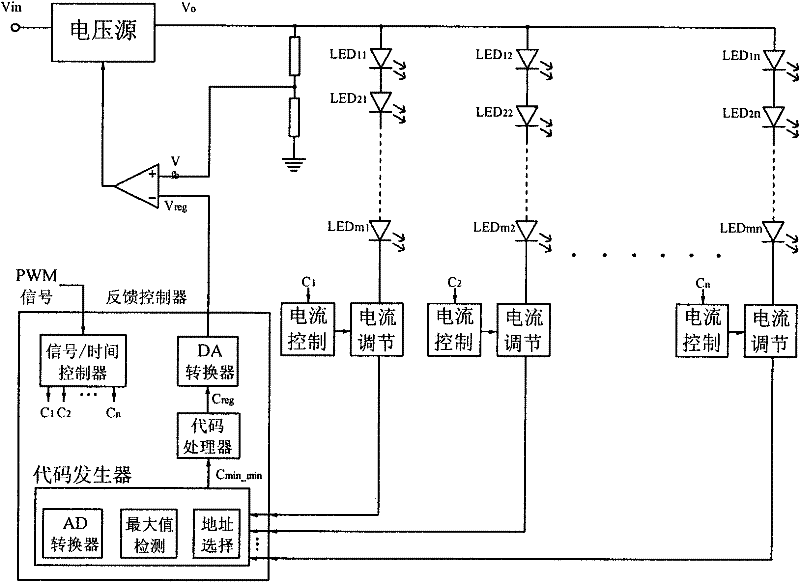
[0023] refer to figure 2 , in the second prior art, digital processing is used to realize sampling and control of the output voltage. This method is accurate and reliable, but the circuit is complicated and the cost is high.

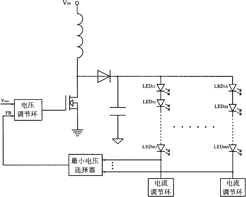
[0024] refer to image 3 In the third prior art, the voltage at both ends of the current regulation loop is sampled, and the minimum voltage value is selected as a feedback signal and a voltage reference signal to be input to the voltage regulation loop, and then a control signal is output to the gate of the main switching tube.

[0025] refer to Figure 4 , in prior art 4, the path with the highest output voltage of the sampling operational amplifier IC has the highest LED voltage drop corresponding to the path with the highest voltage...


PUM


Abstract

The present invention discloses a DC bus voltage following control circuit suitable for multi-path parallel LEDs, which comprises a DC output power source, a DC output voltage control circuit and a load, wherein the output end of the DC output voltage power source is connected with the multi-path load formed by connecting control circuits and LED lamps in series. The present invention is characterized in that one path of highest voltage in the multi-path load is detected out by the DC output voltage control circuit, and a voltage signal which is detected out is converted into a constant circuit signal; the constant circuit signal and a voltage drop voltage signal of a LED are in a special proportion character, and then, a reference signal Vor of output circuit voltage is generated by resistance voltage dividing; the reference signal Vor is sent to the positive input end of a voltage ring as a reference signal; the reference signal is compared with an output voltage sampling signal Vosof another output end of the voltage ring, and a control signal is output to the DC output voltage source to output voltage Vo. The present invention has simple structure, and is suitable for variousconstant control circuits.

Description

technical field [0001] The invention relates to a DC bus voltage following control circuit suitable for multi-channel parallel LEDs. Specifically, it should be a control circuit for making the DC bus voltage always follow the maximum voltage drop of LEDs when the current of multiple LEDs is independently controlled. Background technique [0002] For the application of LED multi-channel constant current control driver, the most commonly used solution is: constant voltage module + multi-channel parallel LED lamp string with constant current control circuit. Since the voltage drop of each LED light string is different, the common methods of constant current control circuit include linear adjustment, PWM chopping control, non-isolated DC-DC constant current circuit (such as BUCK circuit) to control the current in LED. In order to improve the overall efficiency of the driver, it is hoped that the output voltage Vo of the DC voltage source is as close as possible to the voltage V...

Claims


Application Information

Patent Timeline
Patent Type & Authority Applications(China)
IPC IPC(8): H05B37/02
Inventor 吴新科葛良安姚晓莉任丽君
Owner INVENTRONICS HANGZHOU
Why Eureka
Try Eureka