Anesthetic vaporizer charging system
An anesthesia evaporator and liquid injection technology, which is applied in the field of medical equipment, can solve the problems of waste of resources, inability to combine applications of anesthesia machines, etc.
- Summary
- Abstract
- Description
- Claims
- Application Information
AI Technical Summary
Problems solved by technology
Method used
Image
Examples
no. 1 example
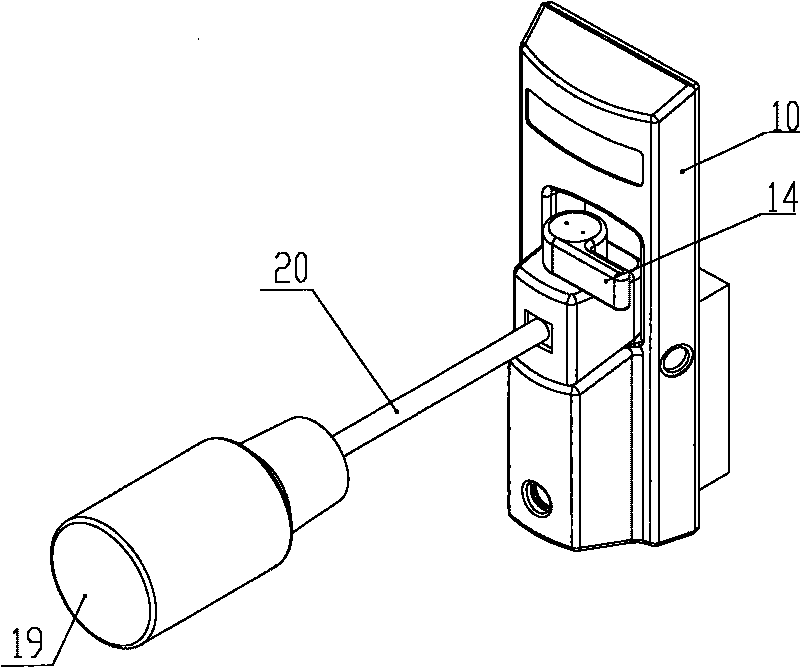
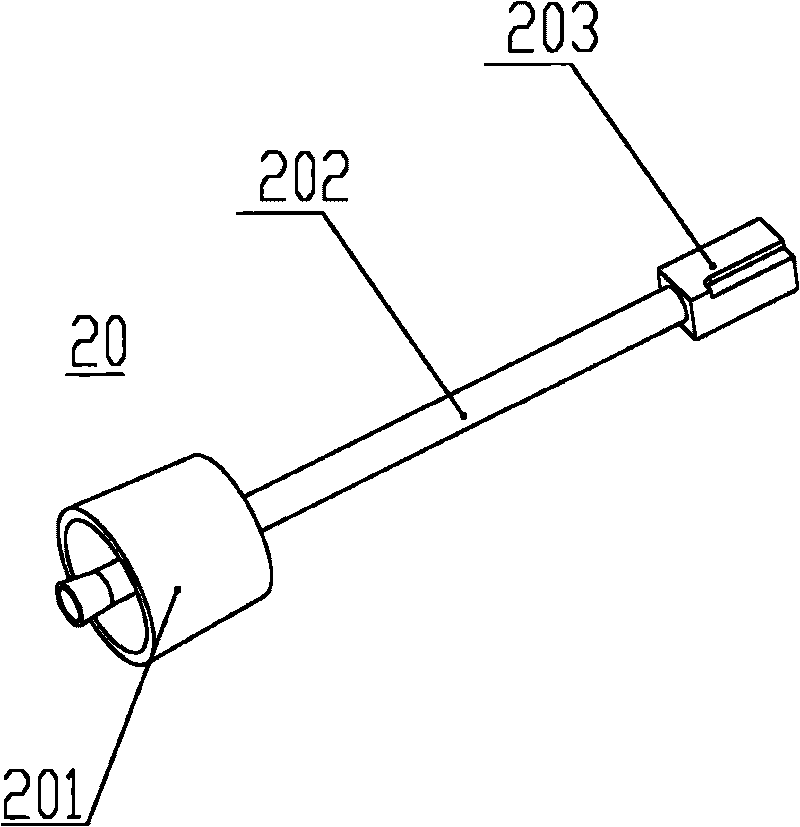
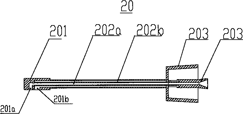
[0037] refer to Figure 1 to Figure 8 , this embodiment shows the application of the plug-in adapter in the present invention. During perfusion, the vial 19 containing the anesthetic agent is mounted on the plug-in adapter 20 (see figure 1 ), the structure of the plug-in adapter 20 is known, and one end 201 is adapted to the existing anesthetic drug bottle 19 for installing the drug bottle, the other end is a plug 203, and the middle is a connecting tube body 202 (see figure 2 ). Specifically, the plug 201 has a liquid inlet 201a and an air inlet 201b, the liquid inlet 201a communicates with the medicine taking port 203b through the channel 202a, and the air inlet 201b communicates with the exhaust port 203a through the channel 202b (see image 3 ), like this, can take medicine from the medicine bottle when the medicine bottle is installed on the plug-in adapter 20.
[0038] In the housing 10 there is a filling seat 1 with which the housing is commercially available from t...
no. 2 example
[0043] refer to Figure 9 to Figure 11 . This example shows the application of the free perfusion method in the present invention. The matching relationship between its cock 21 and the connecting seat 22 is as follows: Figure 10 As shown, that is, the cock 21 is directly screwed on the connecting seat 22 to block the drug inlet of the connecting seat 22 , and the connecting seat 22 is directly installed on the drug feeding port of the liquid injection seat 1 . During perfusion, directly replace the cock 21 with the medicine bottle equipped with the anesthesia machine.
no. 3 example
[0045] refer to Figure 12 to Figure 15 . This example illustrates the use of a quickfiller in the present invention. Fig. 23 has shown the medicine bottle adapter 23 that is used to be installed on the medicine bottle, and this medicine bottle adapter 23 is installed on the connecting seat 24, and this medicine bottle adapter 23 is provided with triggering mechanism, as long as the medicine bottle is screwed on the medicine bottle adapter 23, the trigger mechanism can be started, and the connection seat 24 is given medicine. The concrete structure of the triggering mechanism of medicine bottle adapter 23 can refer to Figure 14 , the trigger mechanism 23 is well known in the rapid perfusion mode and will not be described here. In addition, the medicine bottle adapter can be taken off after filling, and the opening of the connecting seat 24 is blocked by the cock 25, so as to prevent the volatile gas from the anesthesia machine from leaking. In addition, the connection sea...
PUM
 Abstract
Description
Claims
Application Information
 - R&D
- Intellectual Property
- Life Sciences
- Materials
- Tech Scout
- Unparalleled Data Quality
- Higher Quality Content
- 60% Fewer Hallucinations
Browse by: Latest US Patents, China's latest patents, Technical Efficacy Thesaurus, Application Domain, Technology Topic, Popular Technical Reports.
© 2025 PatSnap. All rights reserved.Legal|Privacy policy|Modern Slavery Act Transparency Statement|Sitemap|About US| Contact US: help@patsnap.com


