Drilling fixture for crank positioning pin hole

A technology for positioning pin holes and drilling fixtures, which is used in positioning devices, drilling/drilling equipment, clamping and other directions, can solve the problems of inability to accurately position and process, and it is difficult to meet the drilling accuracy of crank positioning pin holes. The effect of convenient machining, high positioning accuracy, and easy loading and unloading operations

Active Publication Date: 2010-06-30
JIANGSU GANGYANG
View PDF5 Cites 12 Cited by
  • Summary
  • Abstract
  • Description
  • Claims
  • Application Information

AI Technical Summary

Problems solved by technology

In the prior art, the template and the inner end surface of the crank are used for positioning, supplemented by positioning pins to prevent rotation. The drilling jig with this structure can realize positioning processing, but cannot precisely position processing
This kind of indirect positioning drilling jig is difficult to meet the requirements of the drilling accuracy of the crank positioning pin hole

Method used


Image

  • Drilling fixture for crank positioning pin hole
  • Drilling fixture for crank positioning pin hole
  • Drilling fixture for crank positioning pin hole

Examples


Embodiment Construction

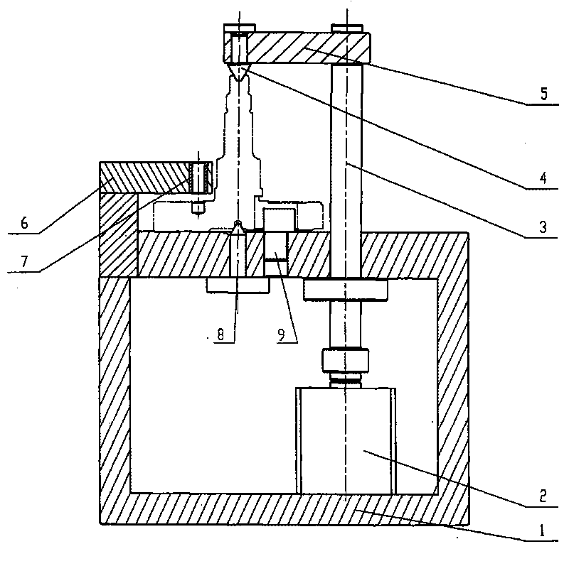
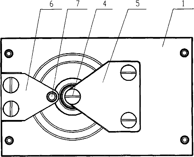
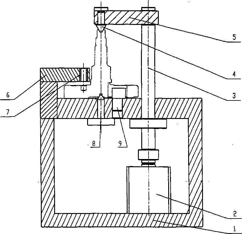
[0013] The present invention will be further described below according to accompanying drawing.

[0014] The crank locating pin hole drilling jig shown in the accompanying drawings comprises a clamp body 1, a cylinder 2, a column 3, an upper top 4, a positioning plate 5, a template 6, a drill sleeve 7, a floating top 8 and a positioning pin 9. In the present invention, the clamp body 1 is a frame-shaped main body member. The cylinder 2 is installed in the inner cavity of the clamp body 1. The top surface is provided with an upward floating top 8 and a positioning pin 9. The left side wall is higher than the top surface and faces the right horizontal connection template 6. The right end of the template 6 is provided with a vertical drill sleeve 7 . The cylinder 2 connected to the column 3 in the inner cavity of the clamp body 1 passes through the top face of the clamp body 1, the top of the column 3 is connected to the right end of the positioning plate 5, and the left end of t...


PUM


Abstract

The invention discloses a drilling fixture for a crank positioning pin hole, which comprises a fixture body, a cylinder, an upright post, an upper tip, a positioning plate, a template, a drilling sleeve, a floating tip and a positioning pin. The drilling fixture realizes initial positioning by utilizing the matching between the outer end surface of a crank and the floating tip at the top end of the fixture body as well as the positioning pin; the cylinder in the fixture body is started to pull the upright post so as to realize the matching between the downward upper tip at the top end of the upright post and an upward central hole of the crank, thereby realizing axial positioning and clamping of the crank; and the crank positioning pin hole is accurately drilled according to the drilling sleeve on the template. With synchronous installing and positioning, synchronous positioning and compacting, good drilling quality, short auxiliary working hours and high production efficiency, the drilling fixture is particularly suitable for mass production and application.

Description

technical field [0001] The invention relates to a machining fixture, in particular to a drilling fixture. Background technique [0002] The crank is the main component of the crankshaft and belongs to special-shaped parts. A positioning pin hole is provided on the inner end surface of the crank, which requires high position accuracy and is difficult to drill. In the prior art, the template and the inner end surface of the crank are used for positioning, and positioning pins are used to prevent rotation. The drilling jig with this structure can realize positioning processing, but cannot precisely position processing. This kind of indirect positioning drilling jig is difficult to meet the requirements of the drilling accuracy of the crank positioning pin hole. Contents of the invention [0003] The invention mainly aims at the deficiencies of the prior art, and proposes a crank positioning pin hole drilling jig with simple positioning structure, accurate positioning and re...

Claims


Application Information

Patent Timeline
Patent Type & Authority Applications(China)
IPC IPC(8): B23Q3/06B23B47/00
Inventor 阮志林陈胜洪
Owner JIANGSU GANGYANG
Why Eureka
Try Eureka