

Pneumatic pipeline transmission system and method for putting in and taking out transmission carrier
A transmission system and pneumatic pipeline technology, applied in the direction of transportation, packaging, conveyors, etc., can solve problems such as complex structures, and achieve the effects of simple setup, good strength, and simple structure
- Summary
- Abstract
- Description
- Claims
- Application Information
AI Technical Summary
Problems solved by technology
Method used
Image

Examples
Embodiment 1
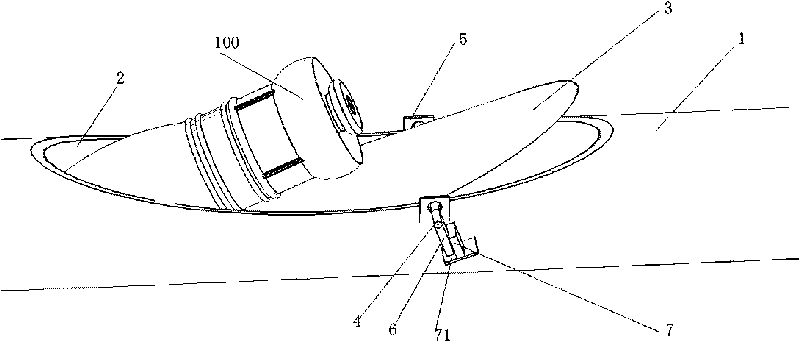
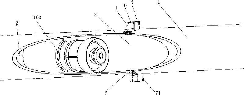
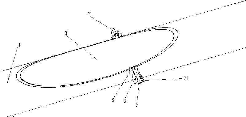
[0054] Such as figure 1As shown, the pneumatic pipeline transmission system of the present invention includes a horizontally arranged transmission pipeline 1, and an outlet and an inlet 2 are provided on the side wall at a predetermined position of the horizontally arranged transmission pipeline 1, and the side wall at the predetermined position is The outlet and the inlet 2 are the same opening, and a cover 3 for closing and opening the outlet and the inlet is provided at the outlet and the inlet. The transport carrier 100 can be put into the transport pipe 1 or taken out from the transport pipe 1 through the outlet and the inlet 2 .
[0055] The pneumatic pipeline transmission system of the present invention, because the outlet and the inlet on the side wall of the transmission pipeline arranged horizontally are 2 same openings, the structural arrangement of the outlet and the inlet is not only simple in structure, but also can ensure that the transmission pipeline has bette...
Embodiment 2
[0070] The basic structure of this embodiment is the same as that of Embodiment 1, except that a rotating shaft is fixed on one side of the cover, and the cover is pivotally connected to the transmission pipe through the rotating shaft, and the The rotating shaft is perpendicular to the short axis direction of the oval opening; the rotating shaft is provided with a rotating drive device.
[0071] The driving device acts to drive the cover to rotate through the rotating shaft, and the cover is lifted away from the side where the rotating shaft is fixed, and the outlet and inlet are opened; the driving device reverses and drives the cover through the rotating shaft. The cover rotates in reverse, and the cover falls back to seal the outlet and the inlet.
[0072] In order to make the transmission carrier running in the transmission pipeline accurately stop at the exit and the entrance, a transmission carrier intercepting device is provided at the position of the exit and the entr...
Embodiment 3
[0074] An embodiment of the present invention provides a method for removing a transmission carrier from a transmission pipeline, which is used for a horizontally arranged transmission pipeline in a pneumatic pipeline transmission system, comprising the steps of:
[0075] S10. Open the cover at the outlet and the inlet of the side wall at the predetermined position of the transmission pipeline, the outlet and the inlet of the side wall at the predetermined position are the same opening;
[0076] S20. The transmission carrier running in the transmission pipeline rushes out of the transmission pipeline from the exit and the entrance.
[0077] In the embodiment of the present invention, the transmission carrier is taken out from the transmission pipeline. Since the transmission carrier running in the transmission pipeline is flushed out of the transmission pipeline from the exit and the entrance of the same opening, not only the exit and the entrance of the transmission pipeline a...
PUM
 Abstract
Description
Claims
Application Information