
Pneumatic pipe transmission system and method

A transmission system and pneumatic pipeline technology, applied in the field of pipeline transmission system, can solve the problems of easy failure, complicated structure setting and control, etc., and achieve the effects of simple structure, reduced failure rate and simple system structure

Inactive Publication Date: 2010-06-30
BEIJING RINRONG TECH
View PDF7 Cites 0 Cited by
  • Summary
  • Abstract
  • Description
  • Claims
  • Application Information

AI Technical Summary

Problems solved by technology

[0005] Set special intake valves at the sending workstation and receiving workstation, and the opening and closing of the intake valves are controlled by the circuit control part. Such a structural setting and its control are relatively complicated and prone to failure

Method used


Image

  • Pneumatic pipe transmission system and method
  • Pneumatic pipe transmission system and method
  • Pneumatic pipe transmission system and method

Examples


Embodiment 1

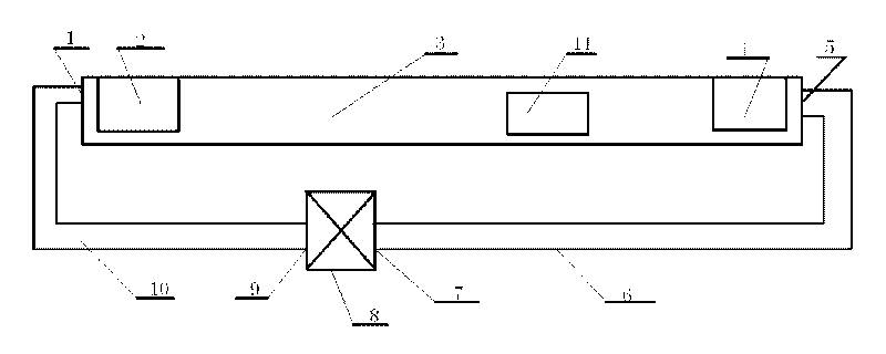
[0076] Such as figure 2 As shown, the pneumatic pipeline transmission system of the present invention includes a horizontally arranged transmission pipeline 3, a sending workstation 2 and a receiving workstation 4 are arranged on the transmission pipeline 3, and a conveyor inlet is provided at the sending workstation 2, A transmitter outlet is provided at the receiving workstation 4, and a door body is provided at the transmitter inlet and the transmitter outlet;

[0077] At the sending workstation 2, an air intake pipeline 10 is connected through the connection part 1, and the air intake pipeline 10 is connected with the wind source device 8 through the connection part 9;

[0078] An air extraction pipeline 6 is connected to the end of the transmission pipeline 3, and the air extraction pipeline 6 is connected to a wind source device 8;

[0079] The conveyor 11 is put into the transmission pipeline 3 by the conveyor inlet, and the air source device 8 connected to the air ex...

Embodiment 2

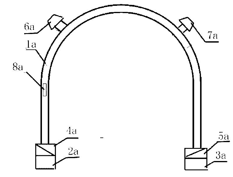
[0092] Such as Figure 6 As shown, the pneumatic pipeline transmission system of this embodiment includes a transmission pipeline 3, and the transmission pipeline 3 includes at least two vertical pipeline parts 13 and an arc connected to the at least two vertical pipeline parts 13. pipe section 13';

[0093] The lower end of the vertical pipeline part 13 is provided with a sending workstation 2 and a receiving workstation 4; a transmitter inlet is provided at the sending workstation 2, a transmitter outlet is provided at the receiving workstation 4, and There are doors at the entrance of the conveyor and at the exit of the conveyor;

[0094] The sending workstation 2 is connected to the air intake pipeline 10 through the positive pressure air source port 1, and the air intake pipeline 10 is connected to the air source device 8 through the connecting part 9;

[0095] At a position close to the receiving station 4 on the transmission pipeline 3, that is, on the connecting bend...


PUM


Abstract

The invention discloses a pneumatic pipe transmission system and a pneumatic pipe transmission method, relates to the field of pipe transmission systems, and solves the problems that the pneumatic pipe transmission system has complex structure and high fault rate in the prior art. The pneumatic pipe transmission system comprises a transmission pipeline. A transmitting work station and a receiving work station are arranged on the transmission pipeline. A transmitter inlet is formed at the transmitting work station, and a transmitter outlet is formed at the receiving work station. A door body is arranged at the transmitter inlet and the transmitter outlet respectively. The transmitting work station is connected with an air inlet line which is connected with an air source device. An air suction line is connected to the transmission pipeline close to the receiving work station, and is connected with the air source device. The pneumatic pipe transmission system and the pneumatic pipe transmission method are applied to the pneumatic pipe transmission.

Description

technical field [0001] The invention relates to the field of pipeline transmission systems, in particular to a pneumatic pipeline transmission system and method. Background technique [0002] Pneumatic pipeline transmission system is a modern and fast logistics transportation tool. The pneumatic pipeline transmission system is used in hospitals, banks, office buildings, supermarkets, production workshops, laboratories and other places where a large number of items need to be transported every day. It can transmit medical records, medical certificates, medicines, laboratory tests, bills, cash, documents and any other items of appropriate size. The items are put into the conveyor when being transported, such as a special transport tube, which ensures that the items are not damaged during the process of transport. The pneumatic pipeline transmission system transmits items from one workstation to another in the pipeline, which can not only effectively ensure the safety of the ...

Claims


Application Information

Patent Timeline
IPC IPC(8): B65G51/04B65G51/32B65G51/06B65G51/18
Inventor 陆洪瑞
Owner BEIJING RINRONG TECH
Learn More