Supercharge Your Innovation With Domain-Expert AI Agents!

Winding drum with speed reducer

A technology of reducer and reel, applied in the direction of hoisting device, spring mechanism, etc., can solve the problems of many intermediate links in power transmission and occupying space, etc.

Inactive Publication Date: 2010-06-30
新乡市鹏升起重设备有限公司
View PDF0 Cites 0 Cited by
  • Summary
  • Abstract
  • Description
  • Claims
  • Application Information

AI Technical Summary

Problems solved by technology

[0002] At present, the rotating power of the drum of the crane is transmitted to the drum transmission shaft by the reducer located outside the drum through the transmission parts such as the output shaft of the reducer, the coupling, and the transmission shaft, and the drum transmission shaft carries the drum together Rotation, the reducer is set outside the reel to occupy a certain space, and there are too many intermediate links in power transmission

Method used


Image

  • Winding drum with speed reducer
  • Winding drum with speed reducer

Examples


Embodiment Construction

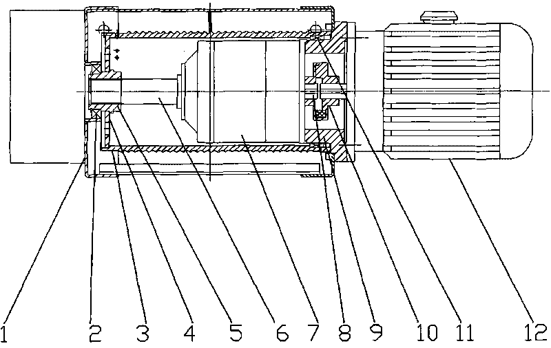
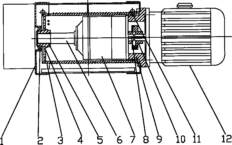
[0006] The present invention will be further described in detail in conjunction with the accompanying drawings. The reducer 7 fixed on the left side of the flange 9 is arranged inside the reel, and the output shaft of the motor 12 fixed on the right side of the flange 9 is connected with the input shaft of the reducer through the coupling 10. 8 are fixedly connected together, the output shaft 6 of the reducer and the left end cover 1 of the box body are connected together in rotation through the bearing 11, the sleeve 5 fixed on the output shaft 6 of the reducer is fixedly connected with the left baffle plate 4 of the reel, and the reel The inner side of the cylinder wall at the right end of the cylinder is connected with the flange 9 through the bearing 11 in rotation. The power of the motor 12 is transmitted to the reducer 7 through the coupling 10, and the reducer 7 transmits the power to the reel through the output shaft 6 of the reducer, and the reel rotates with the outpu...


PUM


Abstract

The invention discloses a winding drum with a speed reducer and aims to provide a winding drum with a speed reducer, having the advantages of small space occupation and few power transmission links. The invention adopts the technical scheme that the winding drum with the speed reducer comprises the winding drum, an electric motor, the speed reducer, a shaft coupler and a left end cover, wherein the speed reducer fixed on the left side of a flange is arranged in the winding drum, an output shaft of the electric motor fixed on the right side of the flange is fixedly connected with a power input shaft of the speed reducer through the shaft coupler, the left end of an output shaft of the speed reducer is rotationally connected with the left end cover, a left baffle plate of the winding drum is fixedly connected with output shaft of the speed reducer, and the inner side of the drum wall on the right end of the winding drum is rotationally connected with the flange through bearings. The winding drum with the speed reducer has the technical effects that because the speed reducer is arranged in the winding drum, and the output shaft of the speed reducer directly transmits power to the winding drum, the winding drum has small space occupation and few power transmission links and saves part of steel.

Description

technical field [0001] The invention relates to a drum on a crane, especially a drum with a reducer. Background technique [0002] At present, the rotating power of the drum of the crane is transmitted to the drum transmission shaft by the reducer located outside the drum through the transmission parts such as the output shaft of the reducer, the coupling, and the transmission shaft, and the drum transmission shaft carries the drum together Rotation, the reducer is set outside the reel to take up a certain space, and there are too many intermediate links in power transmission. Contents of the invention [0003] The purpose of the present invention is to provide a reel with a reducer that occupies less space and has fewer power transmission links. The technical solution of the present invention is completed in this way. The reel with the reducer includes a reel, a motor, a reducer, a coupling, and a left end cover. It is characterized in that the reducer fixed on the left ...

Claims


Application Information

Patent Timeline
Patent Type & Authority Applications(China)
IPC IPC(8): B66D1/30B66D1/12B66D1/22
Inventor 王利剑何志强
Owner 新乡市鹏升起重设备有限公司
Features
  • R&D
  • Intellectual Property
  • Life Sciences
  • Materials
  • Tech Scout
  • Unparalleled Data Quality
  • Higher Quality Content
  • 60% Fewer Hallucinations
Learn More