Electric flow distributor

A flow distributor, electric technology, applied in the direction of fluid circulation arrangements, refrigeration components, refrigerators, etc., can solve the problems of stepping motor out of step or jumping, complicated pipeline connection, high manufacturing cost, etc., to achieve low manufacturing cost, The effect of uniform flow distribution and improved efficiency

Active Publication Date: 2010-06-30
ZHEJIANG SANHUA INTELLIGENT CONTROLS CO LTD
View PDF2 Cites 1 Cited by
  • Summary
  • Abstract
  • Description
  • Claims
  • Application Information

AI Technical Summary

Problems solved by technology

[0004] The technical problem to be solved and the technical task proposed by the present invention are to overcome the problems of large number of parts, high manufacturing cost and complicated pipeline connection in the prior art, aiming at multi-group heat exchangers using multiple heat exchangers or one heat exchanger The refrigeration system of the heat exchanger includes the air conditioning system, providing an electric flow distributor that can perform intelligent flow distribution among multiple heat exchangers or multiple heat exchangers of a heat exchanger, because the electric flow distributor is running There will be a certain cumulative error and the vibration of the system will cause the stepper motor to occasionally lose or skip steps. Therefore, in order to solve the positioning accuracy of the stepper motor, a positioning mechanism is set in the electric flow distributor. During operation or after the system has been running continuously for a period of time, the electric flow distributor can be stopped and positioned once, so that the electric flow distributor can ensure more accurate and intelligent distribution of the flow of the outlet connection, making the operation of the system more economical

Method used


Image

  • Electric flow distributor
  • Electric flow distributor
  • Electric flow distributor

Examples


Embodiment approach

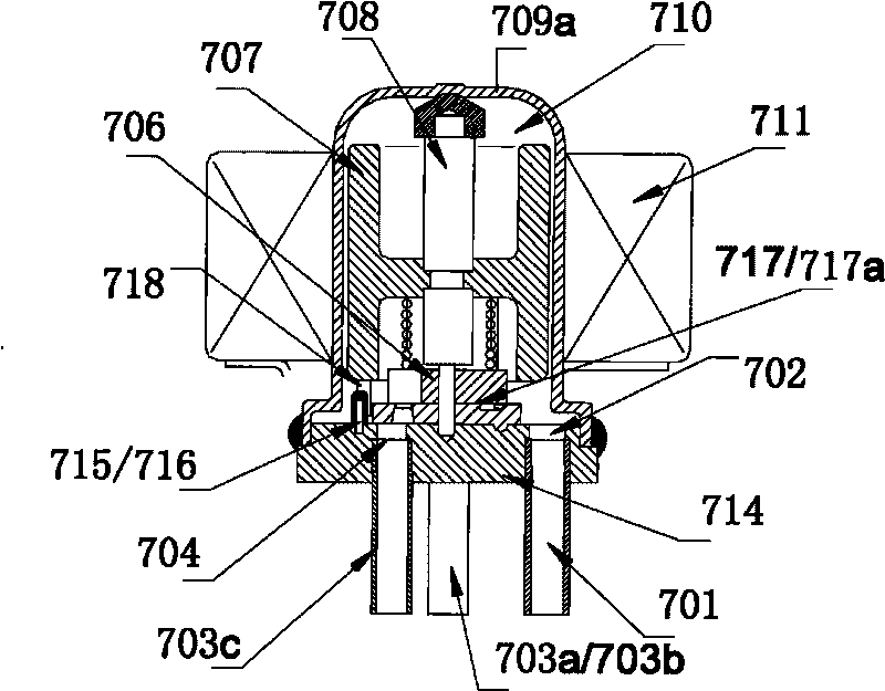
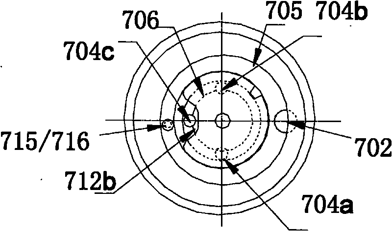
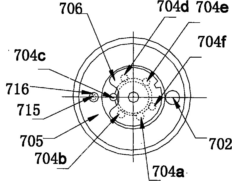
[0034] Such as figure 1 as shown, figure 1 It is a structural schematic diagram of the first embodiment of the electric flow distributor of the present invention, figure 2 for figure 1 The schematic diagram of the local structure of the valve seat and slide valve of the electric flow distributor shown. As shown in the figure, in this embodiment, the electric flow distributor includes a housing 709a. The fixing part in this embodiment is a base part, and the base part includes a base 714 and a bottom plate 717. A valve cavity 710 is formed, and an inlet 702 and a plurality of outlet through holes are also arranged on the base 714, and an inlet connecting pipe 701 communicating with the inlet, and outlet connecting pipes 703a, 703b, 703c communicating with a plurality of outlet through holes are welded and fixed; A coil part 711 as a stator part of the stepping motor is fixed outside 709a, and the casing 709a, the coil part 711 fixed outside the casing 709a, and the base par...


PUM


Abstract

The invention belongs to an electric flow distributor for a refrigerating system, which comprises a casing, an inlet, an inlet connecting pipe, a plurality of outlets, outlet connecting pipes and a stepping motor for driving, wherein the inlet connecting pipe is communicated with the inlet; the outlet connecting pipes are respectively communicated with the outlets. The interior of a valve cavity in the casing is also provided with a driving rod and a slide valve, wherein the driving rod is driven by a magnetic rotor part; the slide valve is arranged opposite to the outlets. The stepping motordrives the slide valve to rotate to realize the flow distribution between the outlets; and the slide valve is also provided with a positioning mechanism, and the position relationship between the slide valve and the outlet is ensured through the positioning of the positioning mechanism; meanwhile,, the system has the advantages of simple installation and connection, and low manufacturing cost.

Description

technical field [0001] The invention belongs to an electric flow distributor for a refrigeration system, in particular to an electric flow distributor for an air-conditioning system. Background technique [0002] Most air-conditioning systems in the prior art include indoor heat exchangers, outdoor heat exchangers, compressors, and throttling devices. The flow distribution has always been a technical difficulty; many systems use electronic expansion valves to individually control each indoor unit and distribute the flow, as disclosed in the publication of the invention patent application number 200610145015.2 filed on November 29, 2006 The solution is to use a control valve module for each indoor unit to intelligently adjust the electronic expansion valve of each indoor unit, so as to realize the on-demand distribution of the refrigerant flow of one-to-many air conditioners. Another example is that the scheme disclosed in the invention patent specification published by the ...

Claims


Application Information

Patent Timeline
Patent Type & Authority Applications(China)
IPC IPC(8): F25B41/00
Inventor 胡梅宴
Owner ZHEJIANG SANHUA INTELLIGENT CONTROLS CO LTD
Why Eureka
Try Eureka