
Automatic optical detection device of online PCB board

An automatic optical detection, PCB board technology, applied in the direction of measuring devices, material analysis through optical means, scientific instruments, etc., can solve the problem of inability to fully and effectively control product quality, inability to effectively achieve full-process detection, full automation and efficiency Discounts and other issues to achieve the effect of improving efficiency, ensuring quality, and ensuring product quality

Inactive Publication Date: 2010-06-30
苏州德天光学技术有限公司
View PDF0 Cites 27 Cited by
  • Summary
  • Abstract
  • Description
  • Claims
  • Application Information

AI Technical Summary

Problems solved by technology

[0002] In the prior art, when detecting defects on PCB boards (printed circuit boards), it is necessary to remove finished or semi-finished PCB boards from the PCB board production line, and test them one by one on the testing equipment. This method is usually called offline. Operation, it is usually impossible to test every product with the offline detection operation method, but adopts the method of random inspection, which not only cannot fully and effectively control the product quality, but also the random inspection is cumbersome, and needs to be tested at each Arranging special personnel responsible for testing at the entrance of the production line will greatly reduce the automation and efficiency of the entire production process. The most important thing is to control the quality of the product, which cannot effectively achieve the whole process of testing.

Method used


Image

  • Automatic optical detection device of online PCB board
  • Automatic optical detection device of online PCB board
  • Automatic optical detection device of online PCB board

Examples


Embodiment Construction

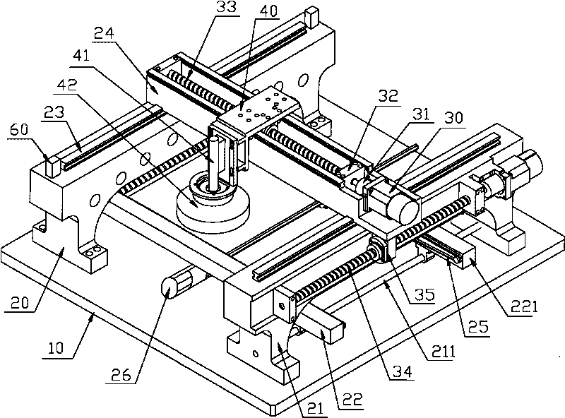
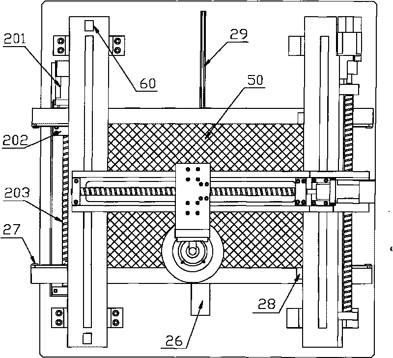
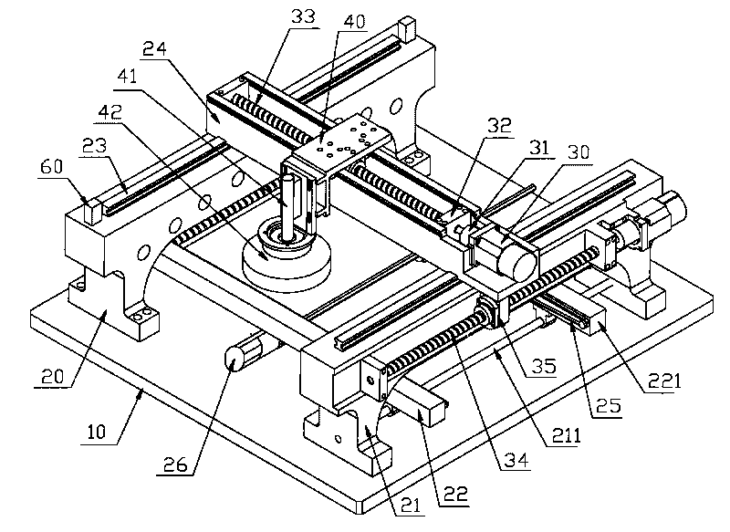
[0012] Such as figure 1 , figure 2 An on-line automatic optical inspection device for PCB boards shown has a base 10, and an entrance arch bridge seat 20 and an exit arch bridge seat 21 are arranged in parallel on both sides of the base 10, and the entrance arch bridge seat 20 and the exit arch bridge seat 21 A guide rail 23 is arranged on the top of the guide rail 23, and the upper cross frame of the guide rail 23 is provided with a sliding connection between the beam seat 24 and the guide rail 23. The transmission device is installed inside the beam seat 24, and the transmission device is composed of a stepping motor 30, a coupling 31, a nut seat 32 and a screw 33. The transmission device is connected to the follower 40 equipped with a detection camera 41 and a light source lampshade 42. The outlet arch bridge seat 21 is provided with a support for connecting a fixed loading platform 22 and adjusting The support bar 211 at one end of the loading platform 221, the fixed loa...


PUM


Abstract

The invention relates to an automatic optical detection device, in particular to the automatic optical detection device of an online PCB board. The automatic optical detection device comprises a base, an inlet arch bridge seat and an outlet arch bridge seat are respectively arranged in parallel on two sides of the base, a guide rail is respectively arranged on the inlet arch bridge seat and the outlet arch bridge seat, a driving belt is arranged on the inner side of a fixing loading platform, which corresponds to an adjusting loading platform, and is correspondingly connected with a hexagonal threaded rod arranged in the middle of the loading platform, and the other ends of the fixing loading platform and the adjusting loading platform are connected with an adjusting device arranged under the inlet arch bridge seat. The invention can be installed in various positions requiring real-time detection of the product on the production line, and can be operated along with the production line synchronously. Moreover, no special personnel are needed for operation, thereby saving labor resources and greatly improving the efficiency of detection. In addition, all the products requiring detection on the production line can be detected 100 percent, thereby ensuring the product quality.

Description

technical field [0001] The invention relates to an automatic optical detection device, in particular to an on-line automatic optical detection device for PCB boards. Background technique [0002] In the prior art, when detecting defects on PCB boards (printed circuit boards), it is necessary to remove finished or semi-finished PCB boards from the PCB board production line, and test them one by one on the testing equipment. This method is usually called offline. Operation, it is usually impossible to test every product with the offline detection operation method, but adopts the method of random inspection, which not only cannot fully and effectively control the product quality, but also the random inspection is cumbersome, and needs to be tested at each Arranging special personnel responsible for testing at the entrance of the production line will greatly reduce the automation and efficiency of the entire production process. The most important thing is the quality control of ...

Claims


Application Information

Patent Timeline
IPC IPC(8): G01N21/956G01N21/01
Inventor 严仕新
Owner 苏州德天光学技术有限公司
Learn More