
Automatic volume displaced type vacuum degasser for transformer oil

A vacuum degassing device, transformer oil technology, applied in the direction of measuring devices, instruments, scientific instruments, etc., can solve the problems of long time-consuming, time-consuming, low efficiency, etc., to improve work efficiency, shorten work time, and improve service life Effect

Inactive Publication Date: 2010-06-30
ZIBO ZHONGHUI INSTR
View PDF0 Cites 12 Cited by
  • Summary
  • Abstract
  • Description
  • Claims
  • Application Information

AI Technical Summary

Problems solved by technology

The disadvantage of this method is that the oscillation, constant temperature and equilibrium treatment of the sample oil in advance is time-consuming and laborious, and it is not suitable for online chromatographic analysis; For the variable diameter piston, first use the vacuum pump to vacuum the system. After the sample oil enters the degassing chamber, the gas in the oil will be precipitated. The characteristic gas in the gas chamber cannot be completely collected, and gas washing technology must be used, so that the effective concentration of the characteristic gas is reduced, which is not conducive to improving the analysis sensitivity of online chromatography, and the use of a vacuum pump is noisy, takes a long time, and the efficiency is relatively low

Method used


Image

  • Automatic volume displaced type vacuum degasser for transformer oil
  • Automatic volume displaced type vacuum degasser for transformer oil

Examples


Embodiment Construction

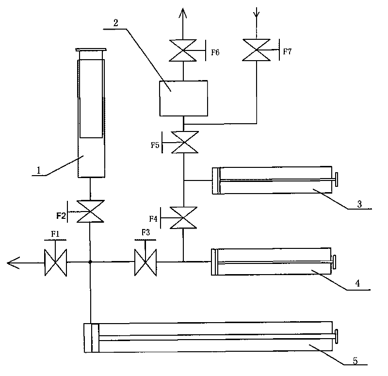
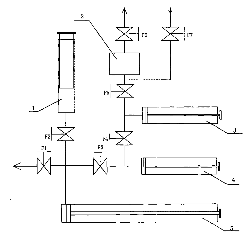
[0010] exist figure 1 In the embodiment, the outlet of the sample oil sampler 1 is respectively connected to the oil sample degassing cylinder 5, the oil discharge valve F1 and the third solenoid valve F3 through the pipeline provided with the second solenoid valve F2, and the other part of the third solenoid valve F3 One end is respectively connected to the gas exchange cylinder 4 and the fourth solenoid valve F4, the other end of the fourth solenoid valve F4 is respectively connected to the gas transfer cylinder 3 and the fifth solenoid valve F5, and the other end of the fifth solenoid valve F5 is respectively connected to the sample gas metering tube 2 And the seventh solenoid valve F7, the other end of the seventh solenoid valve F7 communicates with the carrier gas, and the outlet of the sample gas measuring tube 2 is provided with a sixth solenoid valve F6. The outlet port 2 of the oil discharge valve F1 can be connected to a container for holding waste oil. After the sys...


PUM


Abstract

The invention provides an automatic volume displaced type vacuum degasser for transformer oil. The invention is characterized in that the degasser comprises a sample oil injector, a sample gas quantitative tube, a gas transfer cylinder, a gas exchange cylinder, an oil sample degassing cylinder, an oil draining valve F1 and a plurality of electromagnetic valves; the outlet of the sample oil injector is respectively connected with the oil sample degassing cylinder, the oil draining valve F1 and a third electromagnetic valve F3 by a pipe which is provided with a second electromagnetic valve F2; the other end of the third electromagnetic valve F3 is respectively connected with the gas exchange cylinder and a fourth electromagnetic valve F4; the other end of the fourth electromagnetic valve F4 is respectively connected with the gas transfer cylinder and a fifth electromagnetic valve F5; the other end of the fifth electromagnetic valve F5 is respectively connected with the sample gas quantitative tube and a seventh electromagnetic valve F7; the other end of the seventh electromagnetic valve F7 is communicated with carrier gas; and the outlet of the sample gas quantitative tube is provided with the sixth electromagnetic valve F6. As the preposing degassing device for on-line analysis and monitoring of the oil-gas phase chromatograph of a transformer, the invention has the advantages of high degassing efficiency, quick speed and simple structure, and full-automatic degassing realization.

Description

technical field [0001] The invention provides a volume displacement full-automatic transformer oil vacuum degassing device, which belongs to the field of power system automation. Background technique [0002] At present, more and more power transformers are beginning to install online gas chromatography systems, which can continuously, real-time, online, and automatically analyze the content and growth rate of dissolved gases in transformer oil, and automatically diagnose transformer faults. The object analyzed by the online chromatographic system is the characteristic gas collected from the transformer oil degassing device. At present, there are two main degassing methods for transformer oil: one is the vibration degassing method, which is a commonly used method. Liquid volume equilibrium state, and then extract a certain amount of characteristic gas into the chromatographic system for analysis. The disadvantage of this method is that the oscillation, constant temperature...

Claims


Application Information

Patent Timeline
Patent Type & Authority Applications(China)
IPC IPC(8): G01N30/00
Inventor 许平吉毕海成王志广
Owner ZIBO ZHONGHUI INSTR
Learn More