Combined Degassing and Circulation of Liquid

a liquid and combined technology, applied in liquid degasification, separation processes, instruments, etc., can solve the problem of difficult provision of a mobile phase without or with a low amount of gaseous components

Pending Publication Date: 2020-08-06
AGILENT TECH INC
View PDF4 Cites 4 Cited by
  • Summary
  • Abstract
  • Description
  • Claims
  • Application Information

AI Technical Summary

Benefits of technology

[0004]There may be a need to at least parti...

Problems solved by technology

However, the provision of a mobile phase without or...

Method used


Image

  • Combined Degassing and Circulation of Liquid
  • Combined Degassing and Circulation of Liquid

Examples


Embodiment Construction

[0064]Before describing the figures in further detail, some basic considerations of the present invention will be summarized based on which exemplary embodiments have been developed.

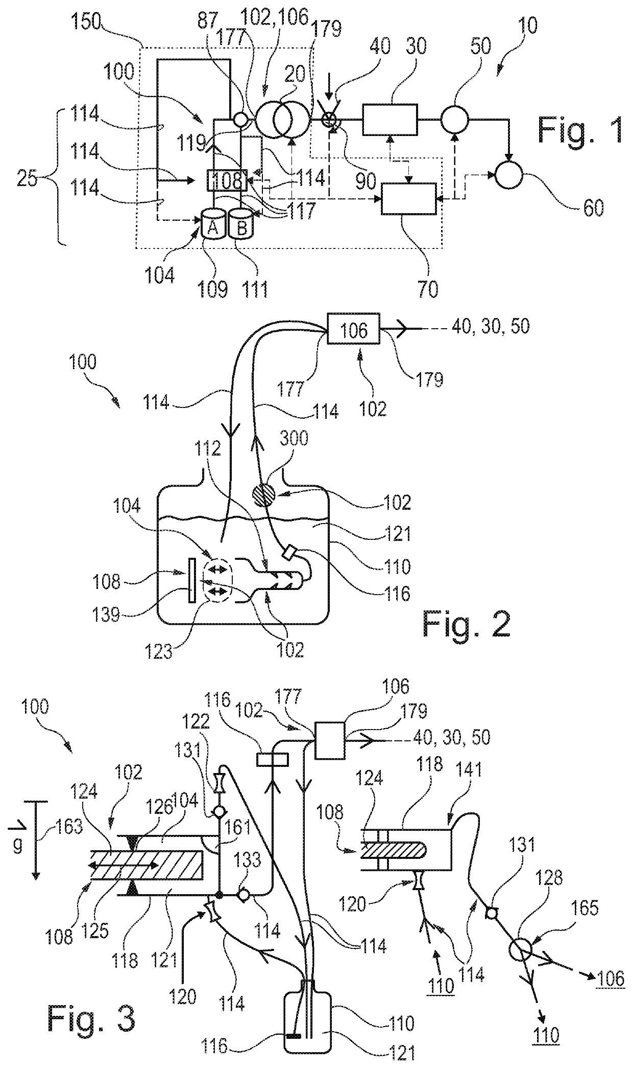
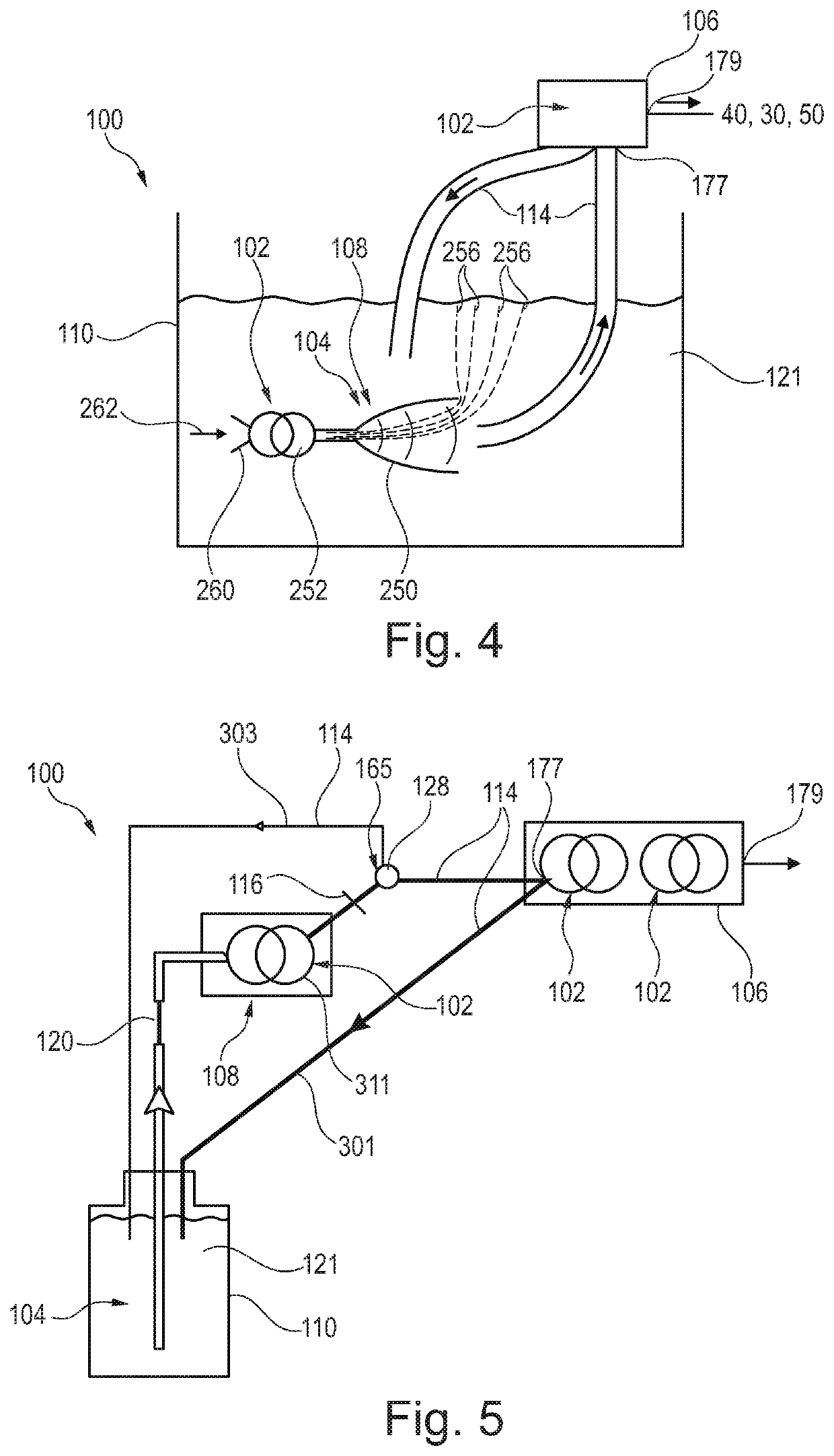
[0065]According to an exemplary embodiment of the invention, a degasser for degassing a gas containing liquid is provided which boosts the degassing function by combining degassing with a circulation of the liquid. Such a degasser may be implemented particularly advantageously in a sample separation device such as a liquid chromatography device, more particularly an HPLC (high performance liquid chromatography) device.

[0066]According to another exemplary embodiment of the invention (which can be combined with or provided separately from the exemplary embodiment described in the previous paragraph), a degasser for degassing a gas-containing liquid is provided which uses a vacuum generating function of a movable body (such as a reciprocating piston) for degassing a gas-containing liquid. With such an archi...


PUM

PropertyMeasurementUnit
Pressureaaaaaaaaaa
Volumeaaaaaaaaaa

Abstract

A degasser for at least partially degassing a gas-containing liquid, in particular for a sample separation device, includes a circulation path along which the liquid can be circulated between a liquid accommodation volume and one of an inlet to a consumer unit consuming degassed liquid or a conduit leading to the inlet, a drive unit configured for circulating the liquid in the circulation path, and a filter in the circulation path for filtering particles or debris out of the liquid, wherein the liquid is forced through the filter by the drive unit. The drive unit includes a movable body, in particular a movable piston or a movable membrane, configured for at least partially degassing the liquid by generating a negative pressure in the liquid.

Description

FIELD OF THE INVENTION[0001]The present invention relates to a degasser for and a method of at least partially degassing a gas-containing liquid, and a sample separation device.TECHNOLOGICAL BACKGROUND[0002]In liquid chromatography, a fluidic sample and an eluent (liquid mobile phase) may be pumped through conduits and a separation unit such as a column in which separation of sample components takes place. The column may comprise a material which is capable of separating different components of the fluidic sample. The separation unit may be connected to other fluidic members (like a sampler or an injector, a detector) by conduits. Before the fluidic sample is introduced into a separation path between a fluid drive unit (in particular a high pressure pump) and the separation unit, a predefined amount of fluidic sample shall be intaken from a sample source (such as a sample container) via an injection needle into a sample loop by a corresponding movement of a piston within a metering ...

Claims


Application Information

Patent Timeline
IPC IPC(8): B01D19/00G01N30/14G01N30/10
CPCB01D19/0031G01N2030/146G01N30/6091G01N2030/027G01N30/14G01N30/10B01D19/00B01D19/0078B01D19/0073B01D35/00G01N30/34G01N2030/322B01D19/0042B01D15/166B01D19/0063B01D19/0094
Inventor SHOYKHET, KONSTANTIN
Owner AGILENT TECH INC
Why Eureka
Try Eureka