Hydraulics for degassing liquids

A hydraulic device and liquid technology, applied in the direction of fluid pressure actuation device, fluid pressure actuation system components, mechanical equipment, etc., can solve the problems of cost generation, easy interference and energy consumption, etc., and achieve high-efficiency degassing, cost durability, low cost effect

Active Publication Date: 2019-09-10
ROBERT BOSCH GMBH
View PDF10 Cites 0 Cited by
  • Summary
  • Abstract
  • Description
  • Claims
  • Application Information

AI Technical Summary

Problems solved by technology

If the degassing is to be carried out by means of ultrasound or vacuum, then additional equipment is required, they generate costs, they increase the susceptibility to interference and consume energy if necessary
Furthermore, these measures can generate additional oil loads

Method used


Image

  • Hydraulics for degassing liquids
  • Hydraulics for degassing liquids
  • Hydraulics for degassing liquids

Examples


Embodiment Construction

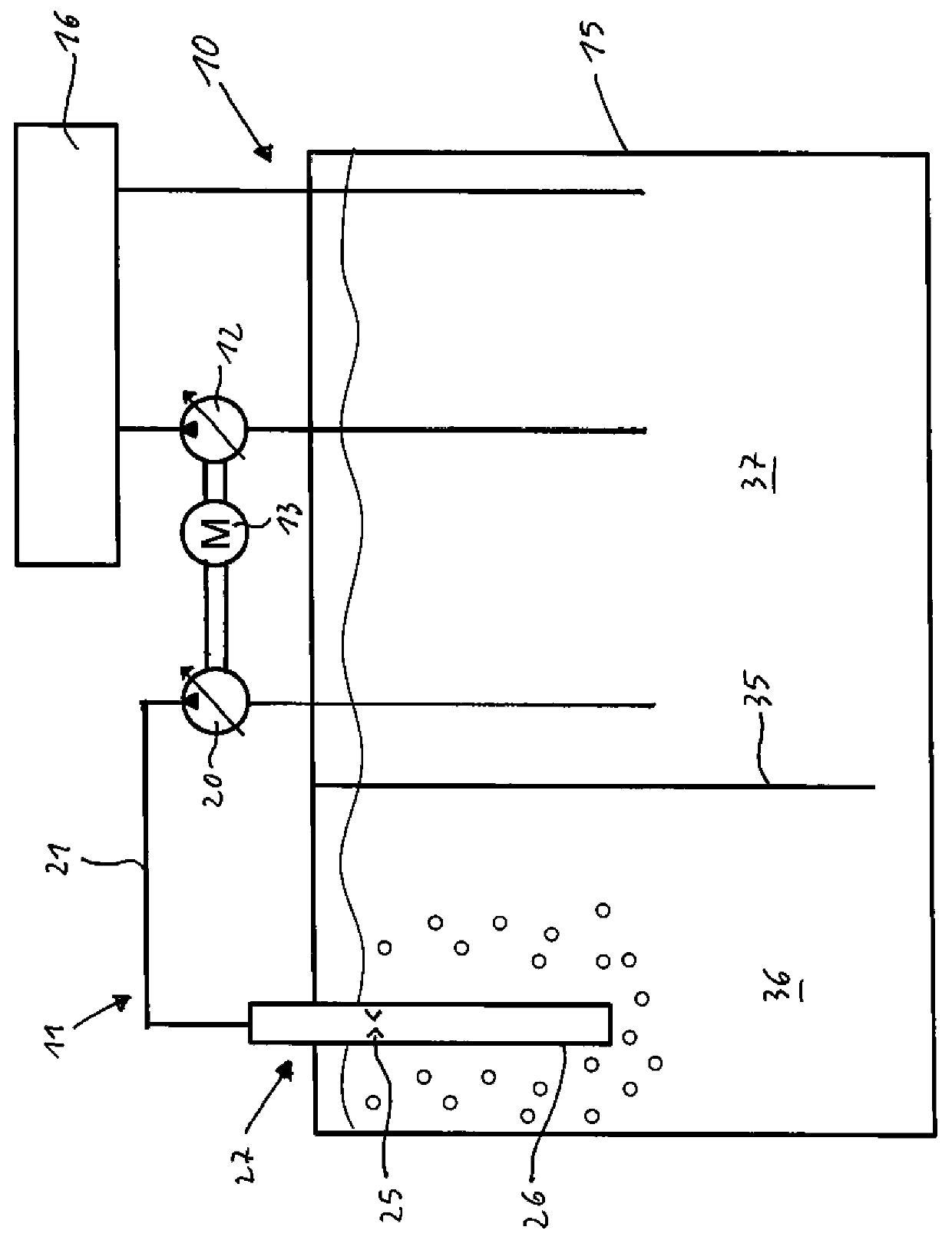
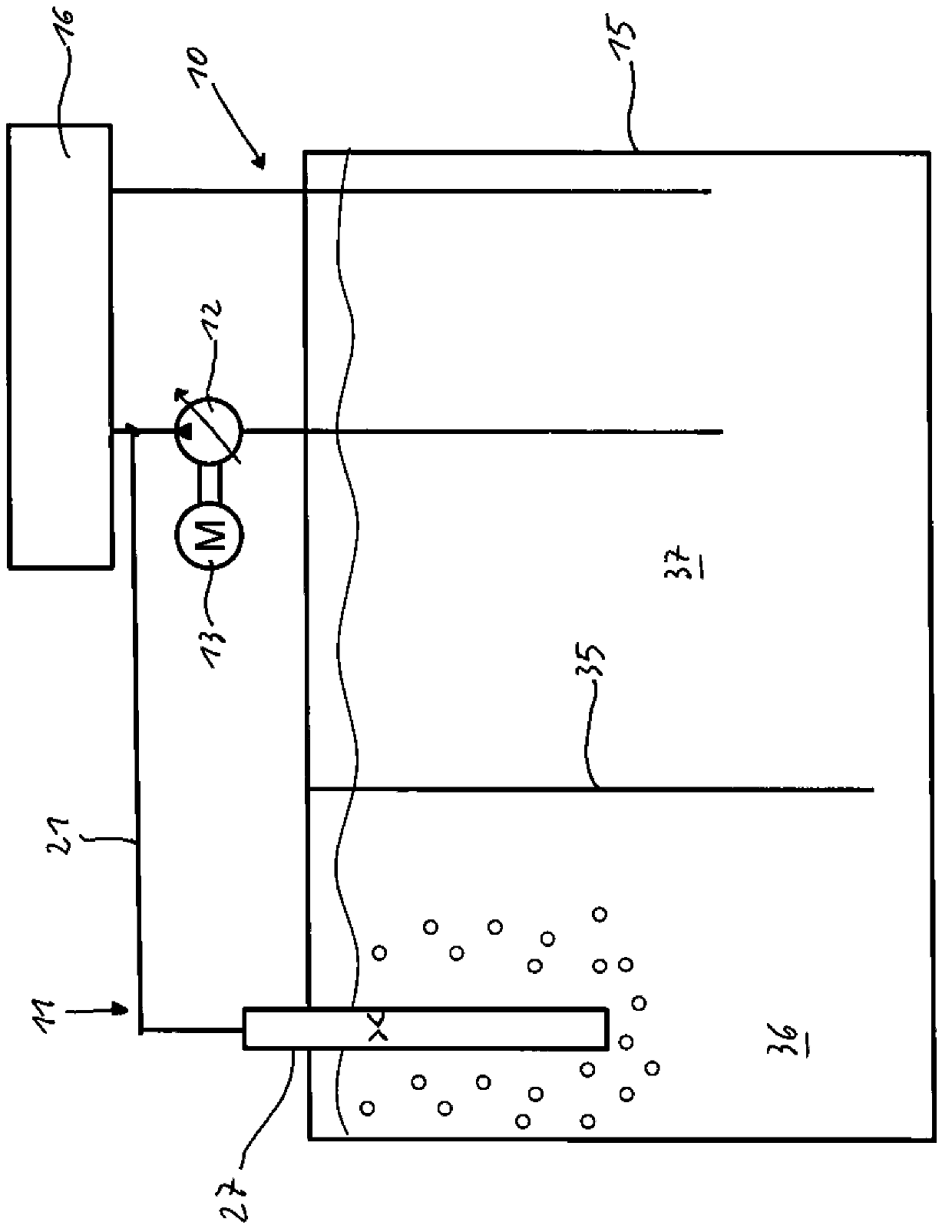
[0028] according to figure 1 The hydraulic equipment includes a hydraulic working circuit 10 and a hydraulic auxiliary circuit 11, which is a device for degassing. A hydrostatic main pump 12 in the form of a squeezer, which is adjustable in its displacement volume and can be driven by a motor 13 , for example an internal combustion engine or an electric motor, belongs to the working circuit 10 . One or more hydraulic consumers are supplied by the squeeze pump 12 via one or more hydraulic valves, optionally with hydraulic fluid, in particular hydraulic oil. The squeeze pump 12 sucks hydraulic fluid from a tank 15 to the hydraulic consumer, from which hydraulic fluid flows back into the tank.

[0029] Hydraulic consumers and hydraulic valves in figure 1 is shown in a greatly simplified manner and generally provided with the reference numeral 16 .

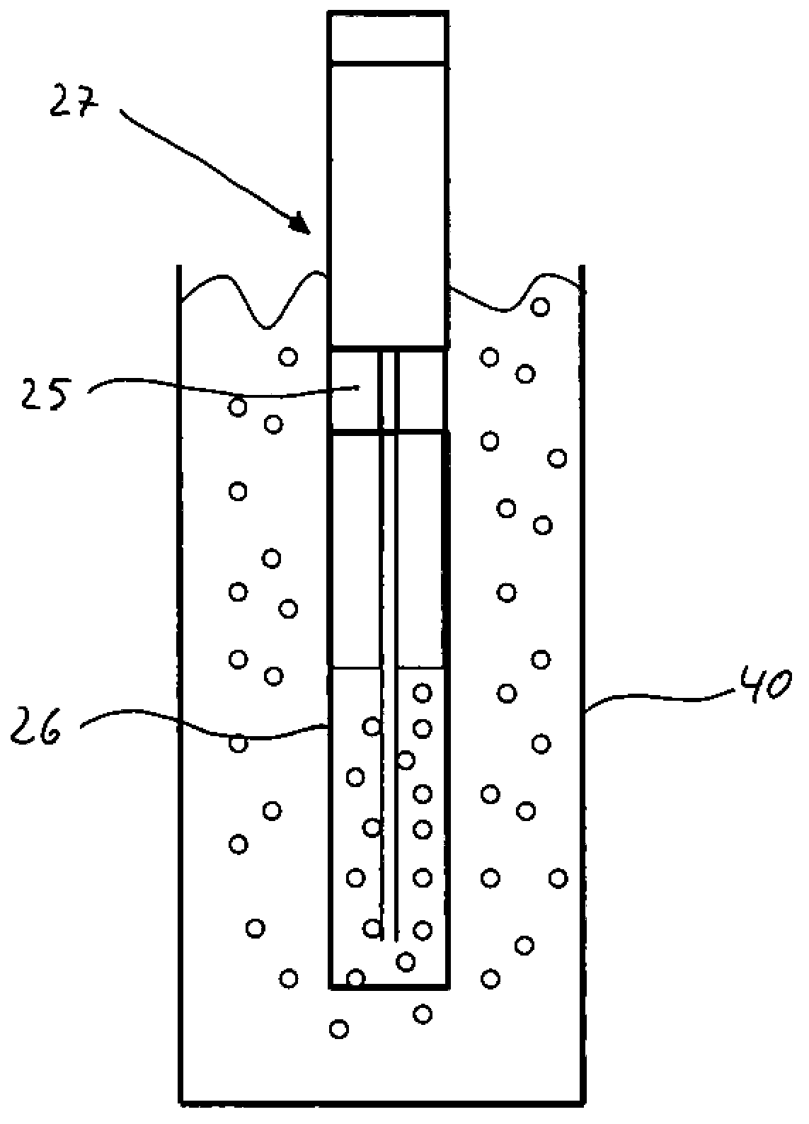
[0030] The hydraulic auxiliary circuit 11 is a separate high pressure circuit and is used for degassing the hydraulic fluid in th...


PUM


Abstract

According to the invention, there is a hydraulic device for degassing liquids, in particular hydraulic oil, said hydraulic device having a pressure source from which the liquid to be degassed flows through nozzles, a pipe connecting to the nozzle, characterized in that the quantity of liquid flowing through the nozzle and the through-flow cross-section of the nozzle are matched to each other such that a liquid jet is produced in the tube by supercavitation downstream of the nozzle , the liquid jet is surrounded by a continuous region of liquid vapor and air.

Description

technical field [0001] The invention relates to a hydraulic device for degassing liquids, in particular hydraulic fluids, having a pressure source from which the liquid to be degassed flows through nozzles, a flow A channel adjoins the nozzle, the flow channel having a significantly larger cross-section compared to the through-flow cross-section of the nozzle. The hydraulic fluid is usually hydraulic oil. Background technique [0002] Air contained in hydraulic fluid is a problem in hydraulic equipment for different reasons. The higher the free or undissolved air fraction, the greater the inherent undesired compressibility of the hydraulic oil. If the hydraulic oil pumped by the pump also contains air bubbles, said hydraulic oil can lead to poor efficiency and high noise levels. The more free air there is in the hydraulic oil, the faster the hydraulic oil ages. Attempts are generally made to lift and vent air bubbles occurring in hydraulic systems from the hydraulic oil ...

Claims


Application Information

Patent Timeline
Patent Type & Authority Patents(China)
IPC IPC(8): F15B21/044
CPCF15B21/044F15B1/26F15B2211/20546F15B2211/20576F15B2211/40507F15B2211/41563F15B2211/611B01D19/0036B01D19/0063B01D19/0094
Inventor M.罗博姆C.伊辛格M-P.米尔豪森
Owner ROBERT BOSCH GMBH
Why Eureka
Try Eureka