Electroless copper plating solution and high-frequency electronic component

a technology of electronic components and copper plating solution, which is applied in the direction of liquid/solution decomposition chemical coating, conductors, fixed capacitor details, etc., can solve the problems of inability to reliably obtain the superior adhesion of copper plating film to the ceramic substrate, and it is not possible to form a copper plating film having a thickness of about 2 .mu.m or more in practi

Inactive Publication Date: 2004-06-01
MURATA MFG CO LTD
View PDF14 Cites 33 Cited by
  • Summary
  • Abstract
  • Description
  • Claims
  • Application Information

AI Technical Summary

Benefits of technology

When an electroless copper plating solution contains tartaric acid or a salt thereof as a complexing agent and does not contain nickel, plating stops before precipitation of copper sufficiently proceeds, and as a result, it has not been possible to form a copper plating film having a thickness of about 2 .mu.m or more in practice. However, with the electroless copper plating solution of the present invention, which contains nickel, the nickel functions as a catalyst for precipitation to allow the copper to continuously precipitate, and hence, the thick copper film generally used for high-frequency conductors can be easily formed.
In addition, when the electroless copper plating solution of the present invention is used in the case in which plating is performed on a ceramic substrate having low surface roughness, the amount of hydrogen generated by decomposition of formaldehyde caused by the effect of the added nickel together with tartaric acid functioning as a complexing agent is decreased. Accordingly, the copper easily precipitates on the low surface roughness ceramic surface and blisters are not developed in the copper plating film, whereby superior adhesion of the copper plating film to the ceramic substrate can be reliably obtained. In addition, since the content of the nickel is small, conductivity equivalent to that of pure copper can be obtained. Furthermore, the nickel added in a small amount also serves to improve the adhesion of the copper plating film to the ceramic substrate in combination with oxygen.
A high-frequency electronic component, such as a dielectric resonator, formed as described above has a copper plating film which is preferably used as a high-frequency conductor, that is, an electrode having a thick copper plating film. Accordingly, superior high-frequency conductivity and a high Qo value can be advantageously obtained.

Problems solved by technology

However, when the roughness of a ceramic surface is decreased and plating is then performed, blisters are developed on the copper plating film, and hence, superior adhesion of the copper plating film to the ceramic substrate cannot be reliably obtained.
When an electroless copper plating solution contains tartaric acid or a salt thereof as a complexing agent and does not contain nickel, plating stops before precipitation of copper sufficiently proceeds, and as a result, it has not been possible to form a copper plating film having a thickness of about 2 .mu.m or more in practice.

Method used


Image

  • Electroless copper plating solution and high-frequency electronic component
  • Electroless copper plating solution and high-frequency electronic component
  • Electroless copper plating solution and high-frequency electronic component

Examples


first example

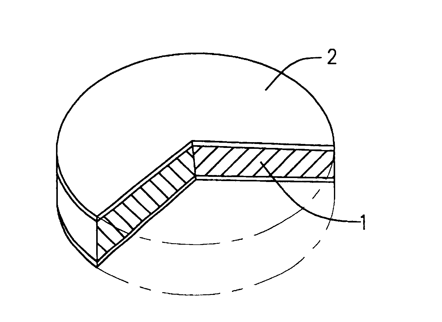
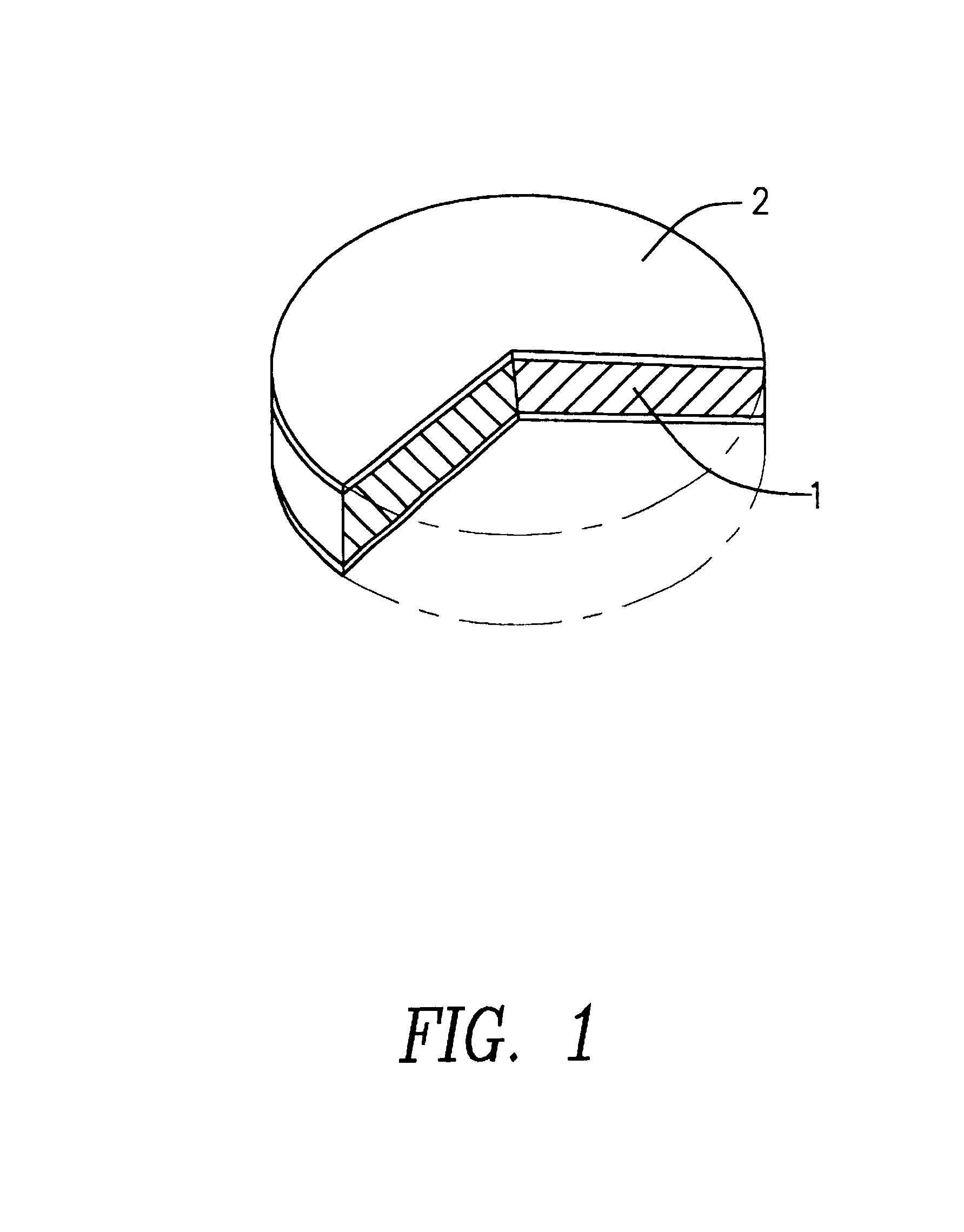
An electroless copper plating solution of this first example comprises copper ions, nickel ions, formaldehyde or a derivative thereof, and tartaric acid or a salt thereof. FIG. 1 is a partially cutaway perspective view of a dielectric resonator, and this dielectric resonator has a copper plating film used as an electrode formed by plating using the electroless copper plating solution of this first example. Hereinafter, the steps of manufacturing a dielectric resonator formed by using an electroless copper plating solution will be described, and the electroless copper plating solution of the first example and the dielectric resonator formed by using the above plating solution will also be described. That is, the dielectric resonator will be described as an example of a high-frequency electronic component.

As a step of manufacturing the dielectric resonator of the first example, disc-shaped ceramic units 1 formed of a mixed ceramic containing BaTi.sub.4 O.sub.9.Ba.sub.2 Ti.sub.9 O.sub....

second example

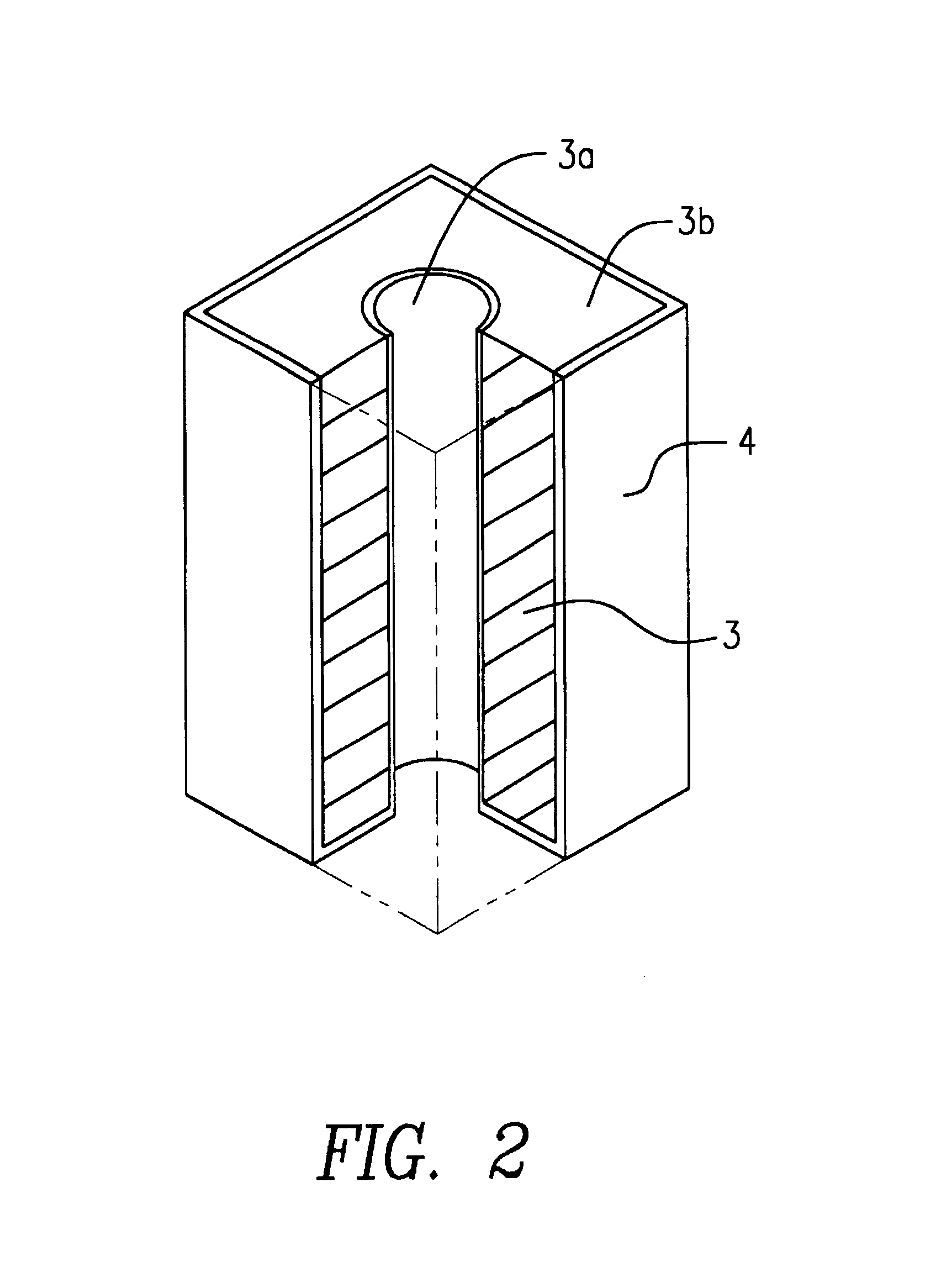
An electroless copper plating solution according to a second example contained copper ions, nickel ions, formaldehyde or a derivative thereof, and tartaric acid or a salt thereof, and the ratio of the content of the nickel ions to that of the copper ions on a molar basis is in the range of about 0.0001 to 0.01. FIG. 2 is a partly cutaway perspective view of a dielectric resonator, and this dielectric resonator has a copper plating film formed by using the electroless copper plating solution in the second example. Hereinafter, the steps of manufacturing a dielectric resonator by using an electroless copper plating solution will be described, and the electroless copper plating solution of the second example and the dielectric resonator having electrodes formed by using this electroless copper plating solution will also be described with reference to the manufacturing steps.

In order to manufacture the dielectric resonator of this second example, a plurality of ceramic units 3, which we...


PUM

PropertyMeasurementUnit
thicknessaaaaaaaaaa
thickaaaaaaaaaa
diameteraaaaaaaaaa

Abstract

An electroless copper plating solution which can ensure superior adhesion of a copper plating film to a flat ceramic surface having low roughness and which can form a high-frequency electronic component having superior high-frequency conductivity and a high Q value is provided. Also provided is a high frequency electronic component formed by using this electroless copper plating solution. The electroless copper plating solution of contains copper ions, nickel ions, formaldehyde or a derivative thereof, and tartaric acid or a salt thereof. The ratio of the content of the nickel ions to that of the copper ions on a molar basis is in the range of about 0.0001 to 0.015.

Description

1. Field of the InventionThe present invention relates to an electroless copper plating solution and to a high-frequency electronic component having a copper plating film formed by using the electroless copper plating solution.2. Description of the Related ArtWhen copper plating films used as high-frequency conductors are formed, an alkaline electroless copper plating solution, which is an aqueous solution containing copper ions, formaldehyde used as a reducing agent, and ethylenediamine tetraacetic acid (EDTA) used as a complexing agent, has generally been used. In addition, a copper plating film approximately 2 to 4 .mu.m thick formed by using an electroless copper plating solution has been used as an electrode in high-frequency electronic components, such as a dielectric coaxial resonator used in the region of 800 to 2,000 MHz or a millimeter wave resonator used in the region of 20 to 30 GHz.In this connection, the superior conductivity of copper plating films has been important ...

Claims


Application Information

Patent Timeline
Patent Type & Authority Patents(United States)
IPC IPC(8): C23C18/40C23C18/16C23C18/31C23C18/48H01B1/02H01G4/008H01P7/04H01P7/10H01P11/00
CPCC23C18/405C23C18/48H01B1/026H01G4/008H01P11/00
Inventor KANOH, OSAMUYOSHIDA, KENJI
Owner MURATA MFG CO LTD
Why Eureka
Try Eureka