
Method for producing injection-molded parts

a technology of injection molding and parts, which is applied in the field of injection molding parts production, can solve the problems of significant energy consumption in relation to the temperature increase of the material, pre-drying of the material, and large installation space requirements of drying plants, and achieve significant energy savings, excellent barrier characteristics, and easy removal of the pre-drying step

Inactive Publication Date: 2010-10-19
KRAUSSMAFFEI TECH GMBH
View PDF18 Cites 0 Cited by
  • Summary
  • Abstract
  • Description
  • Claims
  • Application Information

AI Technical Summary

Benefits of technology

This method significantly reduces energy consumption, eliminates the need for complex drying systems, and allows for high-quality injection-molded parts with improved barrier properties, making the process more energy-efficient and space-saving while maintaining low acetaldehyde content.

Problems solved by technology

Because PET is hygroscopic and because moisture causes a hydrolytic decomposition of polymer chains, the material is pre-dried in a most complex process, in particular when material in granular form is involved.
In this single-screw plasticization with pre-drying, energy consumption is significantly increased in relation to the temperature increase of the material, typically to 0.55 kWh / kg.
In addition, drying plants require significant installation space, which considerably increases the vertical dimensions of the apparatus for producing injection-molded parts.
This plasticizing approach without pre-drying, is not applicable however in certain fields, like for example PET preforms, because there are concerns with respect to hydrolytic decomposition and a possible increase of the acetaldehyde content—AA content—in the melt.
A high AA content hereby adversely affects the taste of the beverages.
Using a twin-screw extruder for producing PET preforms also poses problems with the synchronization of the cyclic operation of an injection molding machine and the continuously operating twin-screw extruder.
Processing such additives with a single screw extruder is presently not possible at all or only with insufficient quality.
Even incorporating 50% titanium dioxide—TiO2-PET master batches—for achieving a 10% TiO2 fraction in a milk bottle, as required for adequate O2 barrier characteristics, is not possible because of the insufficient mixing effect of a single-screw extruder.
Powdered TiO2 cannot be processed with a single-screw extruder, at least not in the required quantity.
However, this requires additional facilities which is time consuming and therefore expensive.

Method used


Image

  • Method for producing injection-molded parts
  • Method for producing injection-molded parts

Examples


Embodiment Construction

[0030]The depicted embodiment is to be understood as illustrative of the invention and not as limiting in any way. It should also be understood that the drawings are not necessarily to scale and that the embodiments are sometimes illustrated by graphic symbols, phantom lines, diagrammatic representations and fragmentary views. In certain instances, details which are not necessary for an understanding of the present invention or which render other details difficult to perceive may have been omitted.

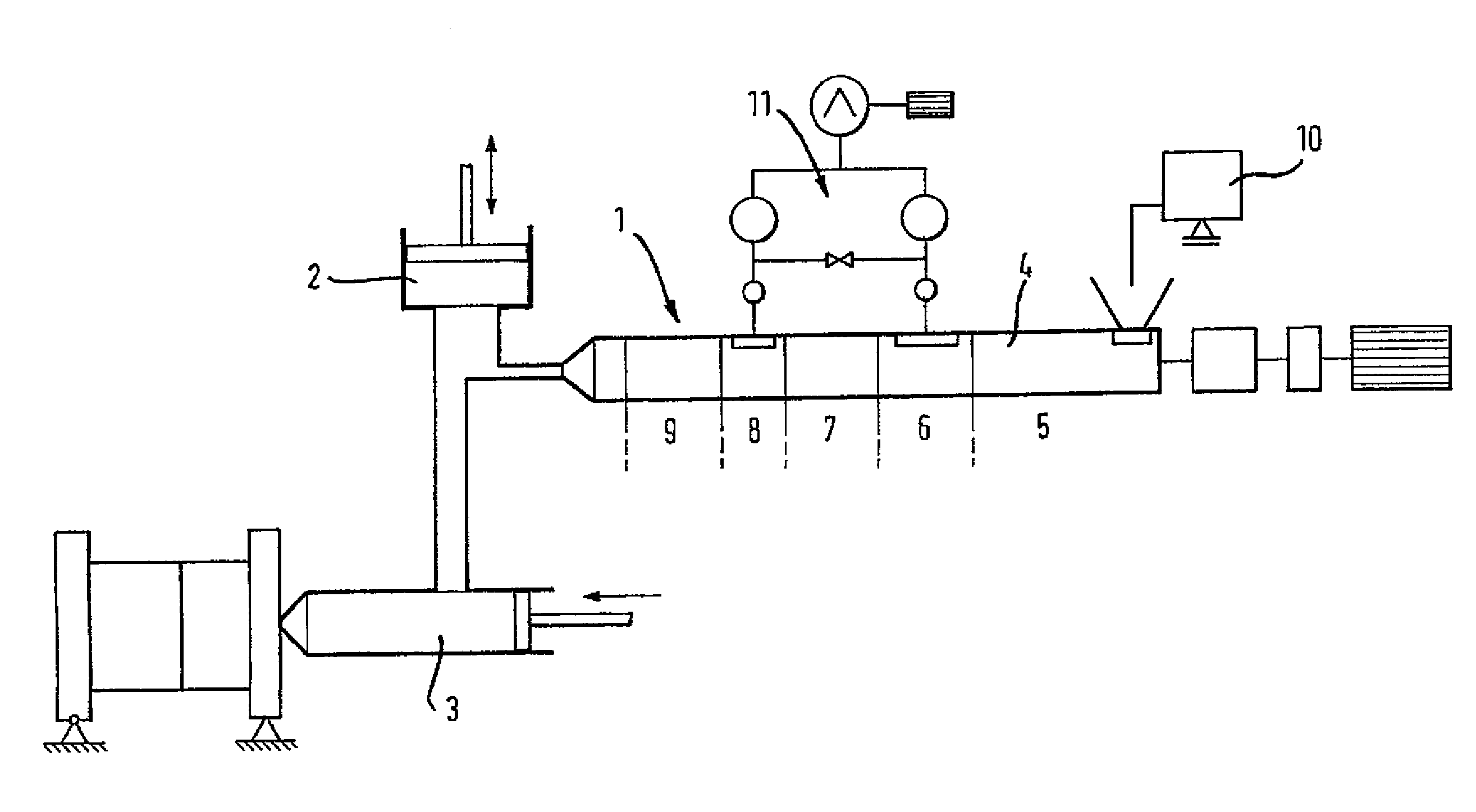
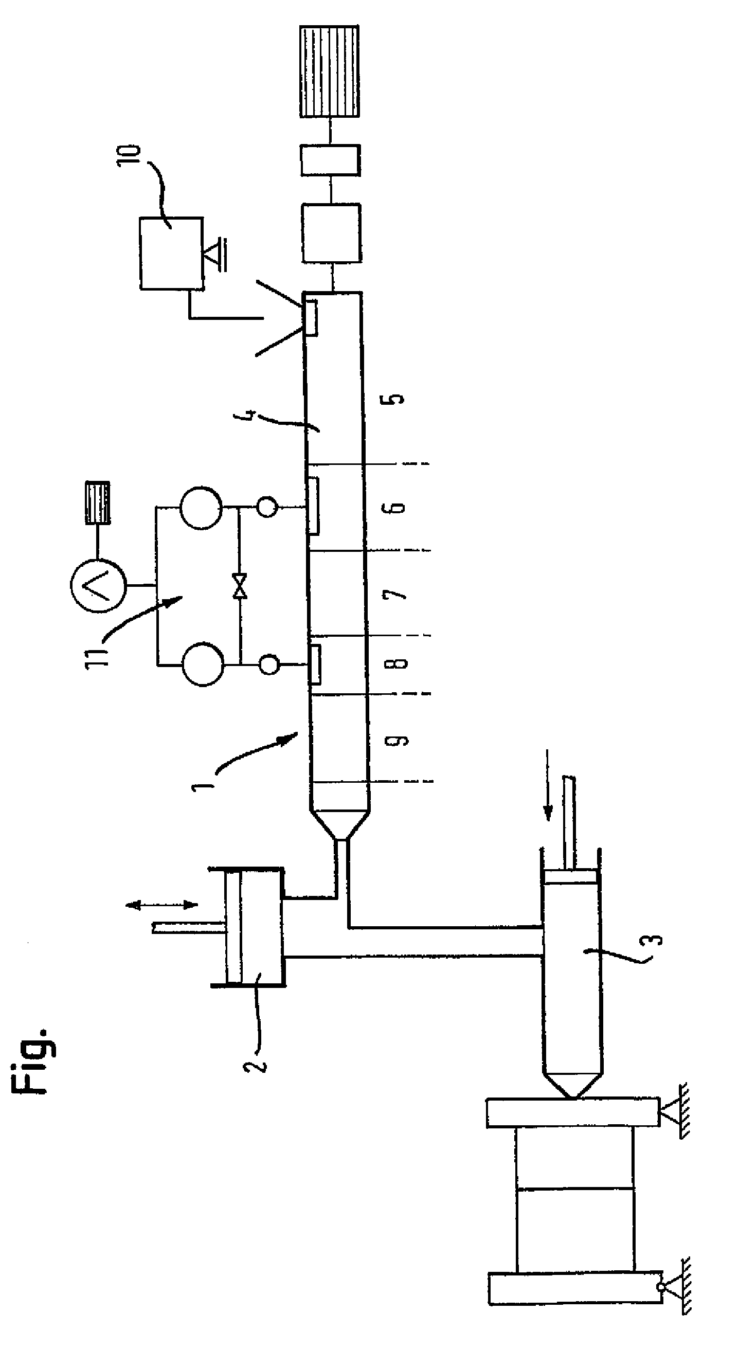
[0031]Turning now to the sole FIGURE, there is shown a schematic illustration of an exemplary embodiment of an apparatus for producing injection-molded parts, in particular PET preforms, in accordance with the invention. The apparatus includes an extruder 1 for processing and plasticizing material in granular form, in this case plastic, and a transfer reservoir 2 for receiving processed and plasticized material as well as a piston unit 3 for subsequent processing of the material. In partic...


PUM

PropertyMeasurementUnit
heightsaaaaaaaaaa
heightaaaaaaaaaa
processingaaaaaaaaaa

Abstract

In a method for producing injection-molded parts, PET material is processed and / or plasticized by means of a twin-screw extruder having a plurality of processing zones. At least two processing zones are implemented as degassing zones. The processed and / or plasticized material is transferred to a transfer reservoir and then further processed by a piston unit.

Description

CROSS-REFERENCES TO RELATED APPLICATIONS[0001]This application is a continuation of prior filed copending U.S. application Ser. No. 11 / 679,528, filed Feb. 27, 2007, the priority of which is hereby claimed under 35 U.S.C. §120, and which is a continuation of prior filed copending PCT International application no. PCT / EP2005 / 052870, filed Jun. 21, 2005, which designated the United States and has been published but not in English as International Publication No. WO 20061024553 A1 and on which priority is claimed under 35 U.S.C. §120, and which claims the priority of German Patent Application, Serial No. 10 2004 041 689.3, filed Aug. 27, 2004, pursuant to 35 U.S.C. 119(a)-(d).[0002]The contents of U.S. application Ser. No. 11 / 679,528, PCT International Application No. PCT / EP2005 / 052870, and German Patent Application, Serial No. 10 2004 041 689.3 are incorporated herein by reference in its entirety as if fully set forth herein.BACKGROUND OF THE INVENTION[0003]The invention relates, in ge...

Claims


Application Information

Patent Timeline
Patent Type & Authority Patents(United States)
IPC IPC(8): B29C45/46B29C47/50B29C45/18B29C45/54B29C45/63B29C48/38B29C48/48B29C48/76
CPCB29C45/1816B29C45/542B29C45/63B29C47/54B29C47/1063B29C47/0014B29K2105/0005B29C2045/466B29K2105/16B29C47/0021B29C48/05B29C48/29B29C48/08B29C48/40B29C48/48
Inventor FISCHBACH, GUNTHERLIEBHOLD, JENSBERNDT, MARKUSZIMMET, RAINERSIEVERDING, MATTHIAS
Owner KRAUSSMAFFEI TECH GMBH
Learn More