Structure and method for measuring resistance of through hole

A technology of resistance measurement and resistance, which is applied in the direction of measuring devices, measuring electrical variables, measuring resistance/reactance/impedance, etc., can solve the problems of inability to measure through-hole resistance, reduce measurement efficiency, and reduce measurement quality, so as to avoid measurement failure , Improving the measurement quality and improving the measurement efficiency

Inactive Publication Date: 2011-10-26
SHANGHAI RES INST OF MICROELECTRONICS SHRIME PEKING UNIV
View PDF4 Cites 0 Cited by
  • Summary
  • Abstract
  • Description
  • Claims
  • Application Information

AI Technical Summary

Problems solved by technology

[0010] 1. The resistance of the through-hole chain is composed of the sum of the resistance of many through-holes and the resistance of the interconnection line corresponding to each through-hole. Therefore, if one or several through-holes in the through-hole chain are defective, the through-hole chain will be open. The measured through-hole chain resistance is infinite, and the through-hole resistance cannot be measured, which reduces the measurement efficiency;
[0011] 2. The through hole in the Kelvin four-point measurement structure is connected to the intersection position of the interconnection line of the adjacent metal layer, that is, it is usually not located at the end point of the interconnection line, but in the actual circuit, the through hole is generally located at the end point of the interconnection line, so through When the measurement structure is used for measurement, the measurement error is large, which reduces the measurement quality

Method used


Image

  • Structure and method for measuring resistance of through hole
  • Structure and method for measuring resistance of through hole
  • Structure and method for measuring resistance of through hole

Examples


Embodiment 1

[0034] Embodiment 1, a two-layer measurement structure with two interconnection lines and one through hole.

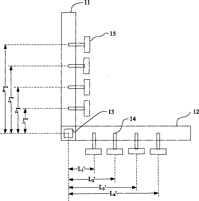
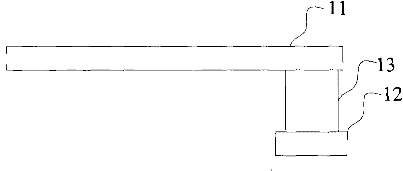
[0035] figure 1 and figure 2 They are the top view and cross-sectional view of the two-layer measurement structure in the first embodiment of the present invention respectively. Combining with this figure, it can be seen that the two-layer measurement structure in this embodiment includes: top-layer interconnection lines 11 and bottom-layer interconnection lines 12, which are respectively connected to communication channels. The top and bottom layers of hole 13; wherein:

[0036] The top-level interconnection lines 11 and the bottom-level interconnection lines 13 are perpendicular to each other and are respectively located in different metal layers in the integrated circuit; and

[0037] The length, width and material of the top-level interconnection line 11 and the bottom-level interconnection line 13 are the same; and

[0038] Four resistance measurement points 1...

Embodiment 2

[0042] Embodiment 2, a three-layer measurement structure with three interconnection lines and two through holes.

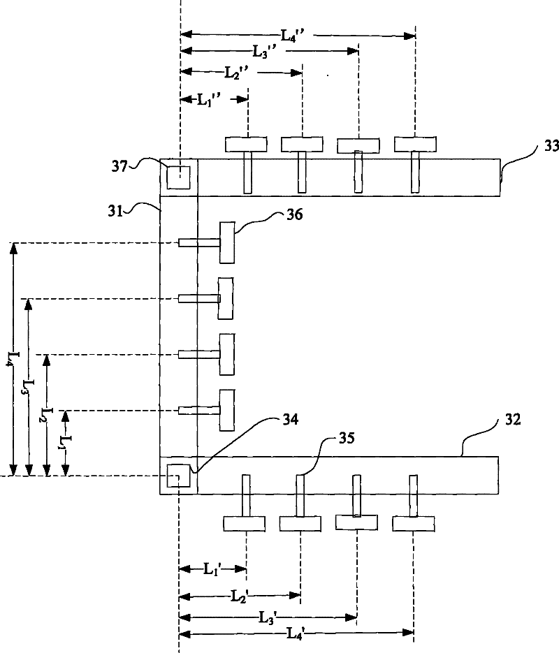
[0043] image 3 It is a top view of the three-layer measurement structure in the second embodiment of the present invention. It can be seen from the figure that the three-layer measurement structure in this embodiment includes three interconnection lines and a first through hole 34 and a second through hole 37;

[0044]Among the three interconnection lines, the two ends of one interconnection line 31 are respectively connected to the top of the first through hole 34 and the bottom of the second through hole 37, and the other interconnection line 32 is connected to the bottom of the first through hole 34. , and the third interconnection line 33 is connected to the top of the second via hole 37 . Among them, the labels 35 and 36 represent the resistance measurement point and the lead terminal respectively, and the label L 1 "~L 4 ” represent the distance from the...


PUM


Abstract

The invention provides a structure and a method for measuring a resistance of a through hole to improve the measurement efficiency and the measurement quality. The structure comprises a plurality of interconnection lines and the through hole, wherein the interconnection lines are vertical with each other, are respectively positioned on different metal layers in an integrated circuit and have the same width and material; each interconnection line is provided with a plurality of resistance measuring points; the top part and the bottom part of the through hole are both respectively connected with one interconnection line; the connecting ends of the through hole and the interconnection lines are positioned at line ends of the interconnection lines; and the connecting ends are covered by the interconnection lines.

Description

technical field [0001] The invention relates to the field of integrated circuits, in particular to a through-hole resistance measurement structure and method. Background technique [0002] With the development of technology, the number of semiconductor devices such as transistors contained in an integrated circuit is gradually increasing. In order to connect semiconductor devices together, a plurality of metal layers are generally arranged in an integrated circuit, and the metal layers are composed of a plurality of interconnection lines on the same layer. The semiconductor device is connected to the interconnection lines of the metal layer through the contact hole, and the interconnection lines of each metal layer are connected through the through hole. [0003] As the number of semiconductor devices included in an integrated circuit increases, the number of metal layers gradually increases, making electrical parameters such as resistance and capacitance of the connection ...

Claims


Application Information

Patent Timeline
Patent Type & Authority Patents(China)
IPC IPC(8): G01R27/04
Inventor 张永红程玉华
Owner SHANGHAI RES INST OF MICROELECTRONICS SHRIME PEKING UNIV
Why Eureka
Try Eureka