Driving mechanism for isolating switch

A technology of driving mechanism and isolating switch, which is applied in the direction of contact driving mechanism, air switch parts, etc., to achieve the effect of improving reliability, small reserved space, and reducing volume

Active Publication Date: 2010-06-30
华精科技股份有限公司
View PDF0 Cites 9 Cited by
  • Summary
  • Abstract
  • Description
  • Claims
  • Application Information

AI Technical Summary

Problems solved by technology

However, this driving mechanism has obvious disadvantages: one is that enough space needs to be reserved in the switch cabinet so that the operating rod can rotate up and down; Mechanism can match with electric mechanism

Method used


Image

  • Driving mechanism for isolating switch
  • Driving mechanism for isolating switch
  • Driving mechanism for isolating switch

Examples


Embodiment 1

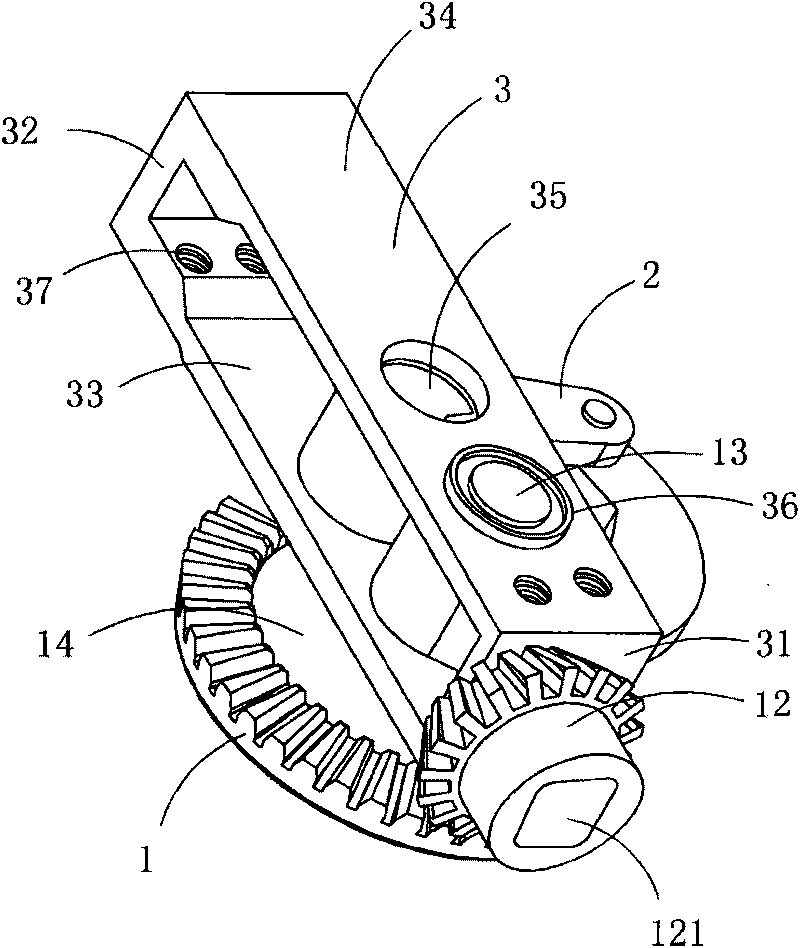
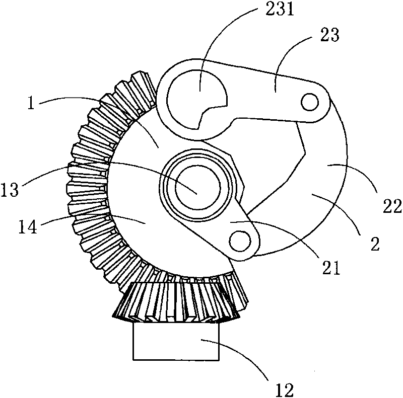
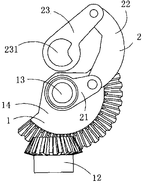
[0016] Figure 1 to Figure 3 A specific embodiment of the invention is shown in which, figure 1 It is a schematic diagram of a three-dimensional structure of the present invention; figure 2 for figure 1 A side view of the drive mechanism shown with the mounting bracket removed; image 3 for figure 2 A schematic diagram of the driving mechanism shown in use.

[0017] This embodiment is a driving mechanism for a disconnector installed in a high-voltage switchgear, see figure 1 , including a gear transmission assembly 1 , a crank arm assembly 2 and a mounting frame 3 . The gear transmission assembly 1 is a vertical axis bevel gear transmission assembly.

[0018] See Figure 1 to Figure 2 , the vertical axis bevel gear transmission assembly includes a first bevel gear 12 that rotates circumferentially along a first rotating shaft (covered in the figure and cannot be seen), is driven by the first bevel gear 12 and rotates circumferentially along a second rotating shaft 13 ...


PUM


Abstract

The invention discloses a driving mechanism for an isolating switch, comprising a gear transmission assembly, a crank arm assembly and a mounting frame, wherein the gear transmission assembly is a vertical shaft bevel gear transmission assembly comprising a first bevel gear and a second bevel gear; the first bevel gear rotates around a first rotating shaft, and the second bevel gear is driven by the first bevel gear and rotates around a second rotating shaft; the first rotating shaft and the second rotating shaft are vertically arranged; the basic shape of the mounting frame is a rectangular framework formed by combining a front wall, a rear wall, a left wall and a right wall; the crank arm assembly comprises a supporting arm fixed on the second rotating shaft, a transmission arm used fordriving an externally connected operation spindle to rotate and a connecting arm used for connecting the supporting arm and the transmission arm; both ends of the connecting arm are respectively connected with the supporting arm and one end of the transmission arm; and when the first bevel gear rotates, the second bevel gear is driven to rotate so as to further drive the supporting arm to rotate,and the externally connected operation spindle is driven to rotate through the connecting arm and the transmission arm. The driving mechanism is suitable for a high-voltage switch cabinet and can effectively reduce the volume of the switch cabinet.

Description

technical field [0001] The invention belongs to the technical field of operating mechanisms of high-voltage electric appliances, and in particular relates to a driving mechanism used in high-voltage isolating switches. Background technique [0002] In the operating mechanism of the traditional isolating switch, the operating handle is generally set directly on the operating spindle, and the operating handle can be turned to drive the operating spindle to rotate to realize the circuit separation and closing; when the isolating switch is used in the switch cabinet, an operating handle can be used The lever is set on the operating spindle, and the operator stands in front of the switch cabinet and directly pulls the operating lever up and down to drive the operating spindle to rotate to realize the opening and closing operation. However, this driving mechanism has obvious disadvantages: one is that enough space needs to be reserved in the switch cabinet so that the operating ro...

Claims


Application Information

Patent Timeline
Patent Type & Authority Applications(China)
IPC IPC(8): H01H31/02H01H3/40
Inventor 童建朋童瑶阳童余阳童微微童扬扬
Owner 华精科技股份有限公司
Why Eureka
Try Eureka