
Method for controlling antenna wave beam to point to moving vehicle, antenna and no-stop parking charge system

A technology for antenna beams and parking charges, applied to antennas, antenna arrays, instruments, etc., can solve problems such as car-following interference, low vehicle speed, and traffic speed affected by the size of the communication coverage area, so as to avoid car-following interference and ensure The effect of transaction time

Inactive Publication Date: 2010-06-30
BEIJING WATCH DATA SYST
View PDF3 Cites 48 Cited by
  • Summary
  • Abstract
  • Description
  • Claims
  • Application Information

AI Technical Summary

Problems solved by technology

[0005] However, due to the fixed time of communication transactions, in order to complete all communication transactions, the speed of vehicles is affected by the size of the communication coverage area.
Such a small communication coverage area will inevitably require a lower vehicle speed
Although the expansion of the communication coverage area can increase the speed of the vehicle, two vehicles will be located in the communication coverage area at the same time, which will cause the following interference problem.

Method used


Image

  • Method for controlling antenna wave beam to point to moving vehicle, antenna and no-stop parking charge system
  • Method for controlling antenna wave beam to point to moving vehicle, antenna and no-stop parking charge system
  • Method for controlling antenna wave beam to point to moving vehicle, antenna and no-stop parking charge system

Examples


Embodiment Construction

[0036] The present invention aims to provide a method for pointing a beam antenna to a moving vehicle, an antenna and a non-stop toll collection system, which can better ensure the passing speed of the vehicle and better avoid following-vehicle interference.

[0037] The present invention will be described in detail below in conjunction with the accompanying drawings and embodiments.

[0038] It should be clear that the described embodiments are only some of the embodiments of the present invention, not all of them. Based on the embodiments of the present invention, all other embodiments obtained by persons of ordinary skill in the art without creative efforts fall within the protection scope of the present invention.

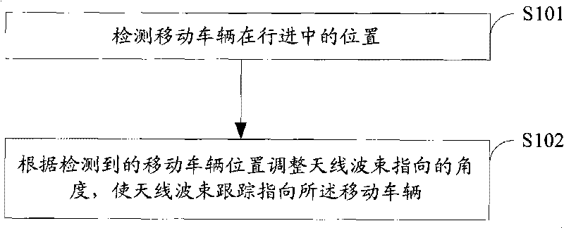
[0039] Such as figure 1 As shown, the method for pointing a beam antenna to a moving vehicle provided in an embodiment of the present invention includes:

[0040] S101, detecting the position of the moving vehicle during travel;

[0041] S102. Adjust an ante...


PUM


Abstract

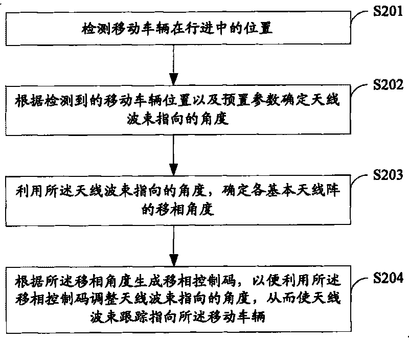
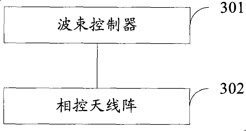
The invention discloses a method for controlling an antenna wave beam to point to a moving vehicle, an antenna and a no-stop parking charge system, which relate to the technical field of antenna and are designed for better ensuring the passing speed of the vehicle and better avoiding the following interference. The method for controlling the antenna wave beam to point to the moving vehicle comprises the following steps: detecting the position of the moving vehicle in the process of running; adjusting the pointing angle of the antenna wave beam according to the detected position of the moving vehicle to control the antenna wave beam to follow and point to the moving vehicle. The antenna comprises a wave beam controller and a phased antenna array, wherein the wave beam controller is used for determining a phase-shifting angle of each basic antenna array in a phased antenna array according to the position of the moving vehicle, and generating a phase-shifting control code according to the phase-shifting angle; the phased antenna array is used for utilizing the phase-shifting control code to adjust the pointing angle of the antenna wave beam in the phased antenna array so as to control the antenna wave beam to follow and point to the moving vehicle. The invention can be used for the no-stop electronic toll collection.

Description

technical field [0001] The invention relates to the technical field of antennas, in particular to a method for directing an antenna beam to a moving vehicle, an antenna and a non-stop charging system. Background technique [0002] The Electronic Toll Collection system (ETC system for short) can use the dedicated short-range communication technology (Dedicated Short Range Communication, DSRC for short) to complete the roadside unit (Roadside Unit, RSU) and on-board unit (On Board Unit, OBU) The two-way communication between the two-way, security authentication and consumption deduction through wireless means, to realize non-stop toll collection, greatly speed up the vehicle traffic, reduce the congestion at the toll ramp, and improve the transport capacity of the road. [0003] The RSU of the non-stop charging system is generally erected on the gantry above the ramp of the toll station. The vehicle equipped with the OBU passes the toll station at a normal speed. Both the RSU ...

Claims


Application Information

Patent Timeline
IPC IPC(8): H01Q3/00H01Q3/30H01Q21/00G07B15/00
Inventor 裴世兵段起志张景秀辛伟孙志强
Owner BEIJING WATCH DATA SYST
Learn More