Eureka AIR delivers breakthrough ideas for toughest innovation challenges, trusted by R&D personnel around the world.

High power factor DCM Boost PFC converter

A high power factor, converter technology, applied in the direction of AC power input conversion to DC power output, output power conversion device, high-efficiency power electronic conversion, etc., can solve the problem of low input power factor, achieve high input power factor, Effects of reduced inductor current ripple and reduced conduction loss

Inactive Publication Date: 2010-06-30
NANJING UNIV OF AERONAUTICS & ASTRONAUTICS
View PDF0 Cites 65 Cited by
  • Summary
  • Abstract
  • Description
  • Claims
  • Application Information

AI Technical Summary

Problems solved by technology

But when the duty cycle is constant in half of the input voltage cycle, its input power factor is low, especially at high voltage input
In some occasions that require high PF value and input current harmonics, the traditional DCMBoost PFC (inductive current discontinuous mode power factor correction) converter is difficult to meet the needs

Method used


Image

  • High power factor DCM Boost PFC converter
  • High power factor DCM Boost PFC converter
  • High power factor DCM Boost PFC converter

Examples


Embodiment Construction

[0024] 1 Working principle of DCM Boost PFC converter

[0025] attached figure 1 It is the main circuit of the Boost PFC converter. For the convenience of analysis, the following assumptions are first made: 1. All devices are ideal components; 2. The output voltage ripple is very small compared with its DC value; 3. The switching frequency is much higher than the input voltage frequency.

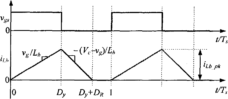
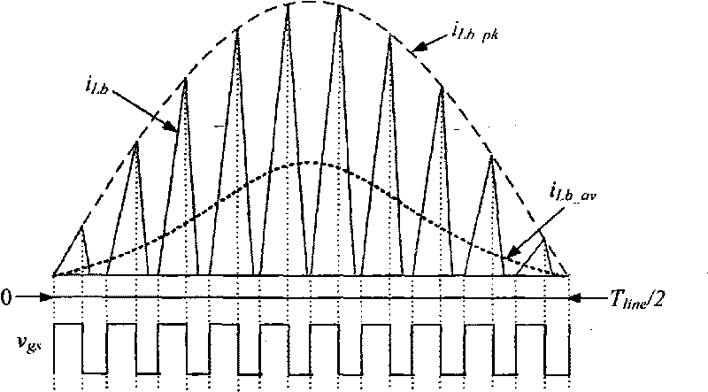
[0026] attached figure 2 The inductor current waveform in one switching cycle during DCM is given. When Q b When turned on, D b cutoff, the boost inductor Lb The voltage across it is v g , its current i Lb start with zero and start with v g / L b The slope increases linearly. When Q b When shutting down, i Lb by D b freewheeling, at this time L b The voltage across it is v g -V o , i Lb With (V o -v g ) / L b the slope of the drop. Since the Boost converter works in DCM mode, before the end of the switching cycle, i Lb down to zero.

[0027] Without loss of generality, le...


PUM


Abstract

The invention relates to a high power factor DCM Boost PFC converter comprising a main power circuit and a control circuit. The main power circuit comprises an input voltage source vin, an EMI filter, a diode rectification circuit RB, a Boost inductor Lb, a switch tube Qb, a diode Db, an output capacitor Co and a load RLd. The high power factor DCM Boost PFC converter is characterized in that the control circuit adopts an output signal which adopts duty ratio as changing rule to drive the switch tube Qb. Adopting the varying duty ratio control, the high power factor DCM Boost PFC converter can improve the PF value to about 1 in the AC input voltage range of 90-265 V, increase the inductance capacity, obviously decrease the inductive current ripple, obviously reduce the effective value of the inductive current and correspondingly reduce the effective value of the current of the switch tube, has high input power factor and small output voltage ripple and contains less input current harmonic waves. The conduction loss of the high power factor DCM Boost PFC converter is reduced, and the efficiency is improved.

Description

technical field [0001] The invention relates to a high power factor DCM Boost PFC converter, belonging to an AC-DC converter of an electric energy conversion device. Background technique [0002] With the development of power electronics technology, the requirements for power conversion devices are getting higher and higher, especially for input power factor (PF) and input current harmonics. Boost converter is one of the most commonly used power factor correction (PFC) circuits. Generally, it can be divided into three types: inductor current continuous mode (CCM), inductor current critical continuous mode (CRM), and inductor current discontinuous mode (DCM). Because the DCM Boost PFC converter has the advantages of zero-current turn-on of the switching tube, no reverse recovery of the diode, constant switching frequency, simple control, and low cost, it has been widely used in low-to-medium power applications. But when the duty cycle is constant in half of the input voltag...

Claims


Application Information

Patent Timeline
Patent Type & Authority Applications(China)
IPC IPC(8): H02M7/217H02M1/14H02M1/42
CPCY02B70/126Y02B70/10Y02P80/10
Inventor 姚凯阮新波冒小晶
Owner NANJING UNIV OF AERONAUTICS & ASTRONAUTICS
Why Eureka
Eureka Blog
Learn More