Shot-peening apparatus, and shot-peening execution method

A shot peening, construction method technology, applied in shot peening. It can solve the problems of difficult recycling of pellets, and achieve the effect of reliable recycling.

Active Publication Date: 2010-06-30
MITSUBISHI HEAVY IND LTD
View PDF1 Cites 6 Cited by
  • Summary
  • Abstract
  • Description
  • Claims
  • Application Information

AI Technical Summary

Problems solved by technology

Therefore, in the technology disclosed in Patent Document 1, when the construction site of shot peening

Method used


Image

  • Shot-peening apparatus, and shot-peening execution method
  • Shot-peening apparatus, and shot-peening execution method
  • Shot-peening apparatus, and shot-peening execution method

Examples


Embodiment 1

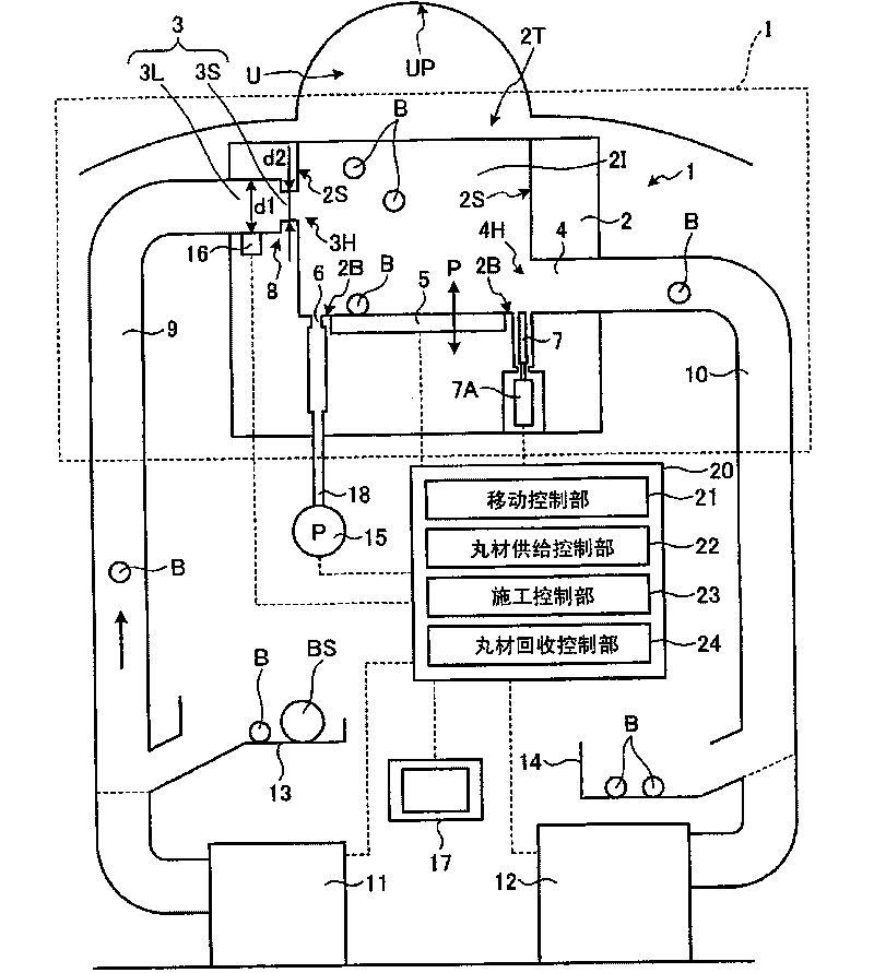
[0065] This invention is suitable for the shot peening of a concave shape part or a convex part shape part. In addition, in this invention, the construction part of shot peening is not limited to a welded part. In addition, the present invention can be fully applied to, for example, the inner and outer surfaces of steam generator inlet and outlet sockets used in power generation equipment, fluid piping, pressure vessels, etc., where shot peening is required, and the application objects of the present invention are not particularly limited. . In addition, the present invention is particularly effective when performing shot peening in a closed space.

[0066] This embodiment is characterized in that the shot material used for the construction of shot peening is collected from the shot peening apparatus by suction at the construction site, and then the shot peening apparatus is moved from the construction site. First, the structure of the shot peening apparatus of this embodime...


PUM


Abstract

Disclosed is a shot-peening apparatus (1) comprising a storage container (2) for storing shot members (B) to impinge on a shot-peening executed portion (U), an exciting device (5) for accelerating the shot members (B), a shot-member outlet (4) formed in the storage container (2) and connected to a shot-member recovery passage (10) to recover the shot members (B) from a container inside (2I), for extracting the shot members (B) in the container inside (2I) to the shot-member recovery passage (10), and a shot-member inlet (3) disposed in the storage container (2) and connected to a shot-member supply passage (9) to supply the shot members (B) to the container inside (2I), for supplying the shot members (B) from the shot-member supply passage (9) to the container inside (2I).

Description

technical field [0001] The present invention relates to shot peening. Background technique [0002] Shot peening is a type of cold working. Shot peening, which is a sphere of ferrous or non-ferrous metal, hits the metal surface at high speed to generate compressive stress on the metal surface and improve the fatigue strength against repeated loading. In a pressure vessel of a chemical plant, a nuclear reactor vessel, etc., for example, in order to improve the fatigue strength of the welded joint, shot peening is performed on the welded portion. Patent Document 1 discloses an ultrasonic shot peening apparatus for shot peening the J-welded portion of the lower surface of the nuclear reactor vessel cover and the stem, and the surface adjacent to the J-welded portion. [0003] Patent Document 1: Japanese Unexamined Patent Publication No. 2006-346775 (0015, Fig. 2, image 3 ) [0004] In the technology disclosed in Patent Document 1, an oscillator is arranged in the recovery ho...

Claims


Application Information

Patent Timeline
IPC IPC(8): B24C1/10
CPCB24C5/005B24C1/10Y10T29/479
Inventor 藤田淳山本刚神吉厚之半田充渡边吉弘服部兼久佐佐木省悟
Owner MITSUBISHI HEAVY IND LTD
Why Eureka
Try Eureka