
Micro-bit and processing apparatus using the micro-bit

A technology of micro-drills and tools, applied in the field of processing tools and carbide micro-drills, can solve the problems of large friction between the drill tip and the PCB board, reduced drill size, broken drills, etc., to improve the symmetry of the single groove, reduce the Small size, not easy to break the drill effect

Active Publication Date: 2010-07-07
SHENZHEN JINZHOU PRECISION TECH
View PDF0 Cites 11 Cited by
  • Summary
  • Abstract
  • Description
  • Claims
  • Application Information

AI Technical Summary

Problems solved by technology

[0003] Due to the structural limitation of the main cutting edge of the existing micro-drill, the friction between the drill tip and the PCB board is large during drilling, which will easily cause the drill to break
With the development of PCB technology, the drilling diameter is required to be smaller and smaller. For micro drills, as the size of the drill decreases, the existing structure has a more significant impact on the broken drill, which limits the further reduction of the drill size. possibility of

Method used


Image

  • Micro-bit and processing apparatus using the micro-bit
  • Micro-bit and processing apparatus using the micro-bit
  • Micro-bit and processing apparatus using the micro-bit

Examples


Embodiment Construction

[0027] Attached below picture and Preferred embodiments further illustrate the present invention.

[0028] The structure of the first embodiment of the micro drill bit of the present invention is as Figure 4- 7, the shown micro drill includes a drill tip 3 and a drill body 4, and the drill tip 3 includes a main cutting edge 31, two auxiliary cutting edges, and three minor cutting edges 32; The edge includes a first auxiliary cutting edge 301 and a second auxiliary cutting edge 302; between the first auxiliary cutting edge 301 and the first relief surface of the drill point, the second relief surface and between the third relief surface 16 and the fourth relief surface The intersecting line 33 that forms between knife face 17 intersects, and makes the length of intersecting line 33 less than the length of micro-drill diameter; Described secondary cutting edge 32 is connected with main cutting edge 31 and two auxiliary cutting edges respectively; Wherein, The main cutting ...


PUM


Abstract

The invention discloses a micro-bit and a processing apparatus using the micro-bit. The micro-bit comprises a bit tip and a bit body, wherein, the bit body is provided with a spiral chip pocket; the bit tip includes a main cutting edge, at least two assistant cutting edges, and at least three subsidiary cutting edges respectively connected with the main cutting edge and the assistant cutting edges. At least two assistant cutting edges are added to substitute the existing one main cutting edge and a main cutting edge is added in the invention, thereby the cutting edge parts of the micro-bit are stressed at more points and the bit tip part of the micro-bit is strengthened in rigidity and not easy to be broken, and the size of the micro-bit can be further reduced on premise of guaranteeing enough rigidity. The processing apparatus using the micro-bit in the invention can ensure the aperture of the drilled hole to be smaller and the processing precision to be higher.

Description

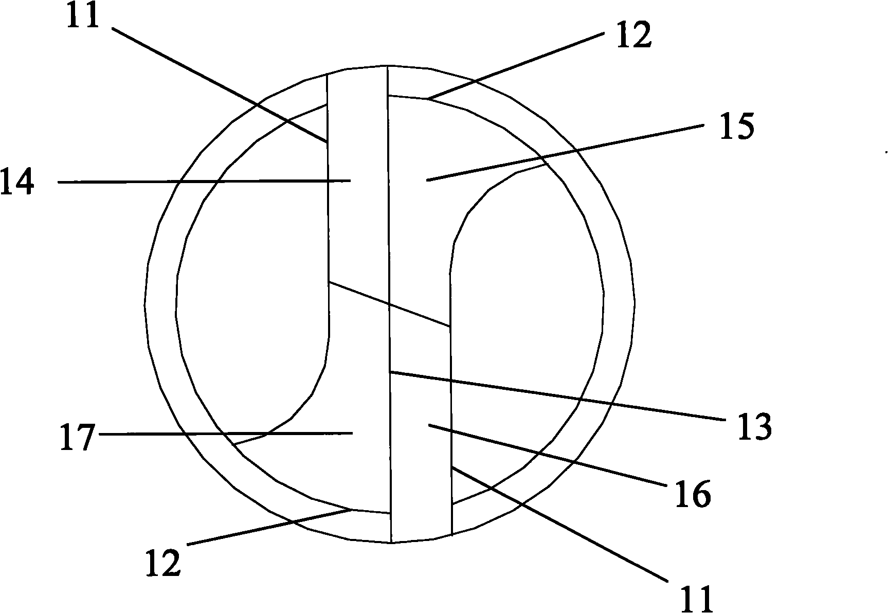
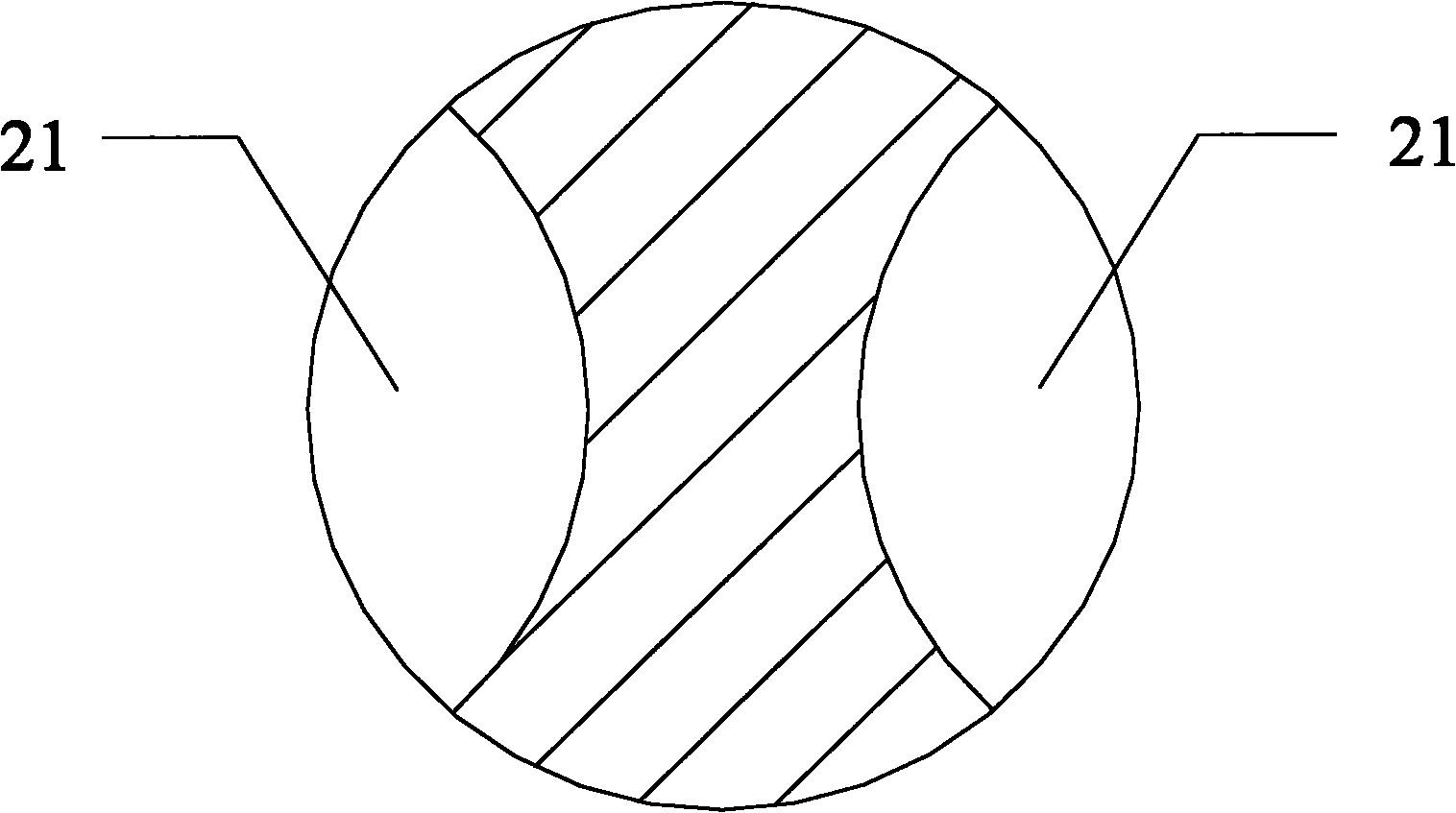
technical field [0001] The invention relates to the manufacturing field of printed circuit boards (PCB for short), and more specifically, relates to a hard alloy micro-drill used for PCB circuit boards and a processing tool using the micro-drill. Background technique [0002] The structure of the commonly used PCB micro-drills is as follows: Figure 1 - Figure As shown in 3, the micro drill includes a drill point 1 and a drill body 2, and the shape of the drill point is as follows figure 2 As shown, there are two symmetrical main cutting edges 11, a chisel edge between the two main cutting edges, and two helical secondary cutting edges 12 positioned at the rear side of the main cutting edge; the main cutting edge Between the cutting edge and the minor cutting edge and the chisel edge, such as picture The first relief surface 14, the second relief surface 15, the third relief surface 16, and the fourth relief surface 17 shown in ; the first relief surface 14 and the second...

Claims


Application Information

Patent Timeline
Patent Type & Authority Applications(China)
IPC IPC(8): B23B51/02
Inventor 屈建国肖真健邹卫贤张辉
Owner SHENZHEN JINZHOU PRECISION TECH
Learn More