NC (numerical control) processing method for special-shaped joint part

A special-shaped joint and processing method technology, applied in the field of joint parts, can solve the problems of parts clamping deformation, difficult-to-machine materials, clamping deformation, etc.

Inactive Publication Date: 2010-07-07
SHENYANG LIMING AERO-ENGINE GROUP CORPORATION
View PDF0 Cites 28 Cited by
  • Summary
  • Abstract
  • Description
  • Claims
  • Application Information

AI Technical Summary

Problems solved by technology

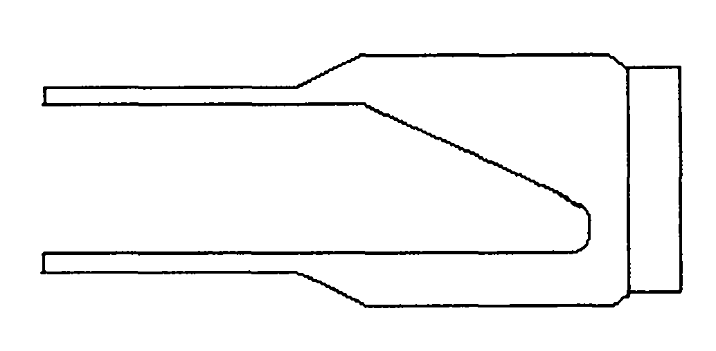
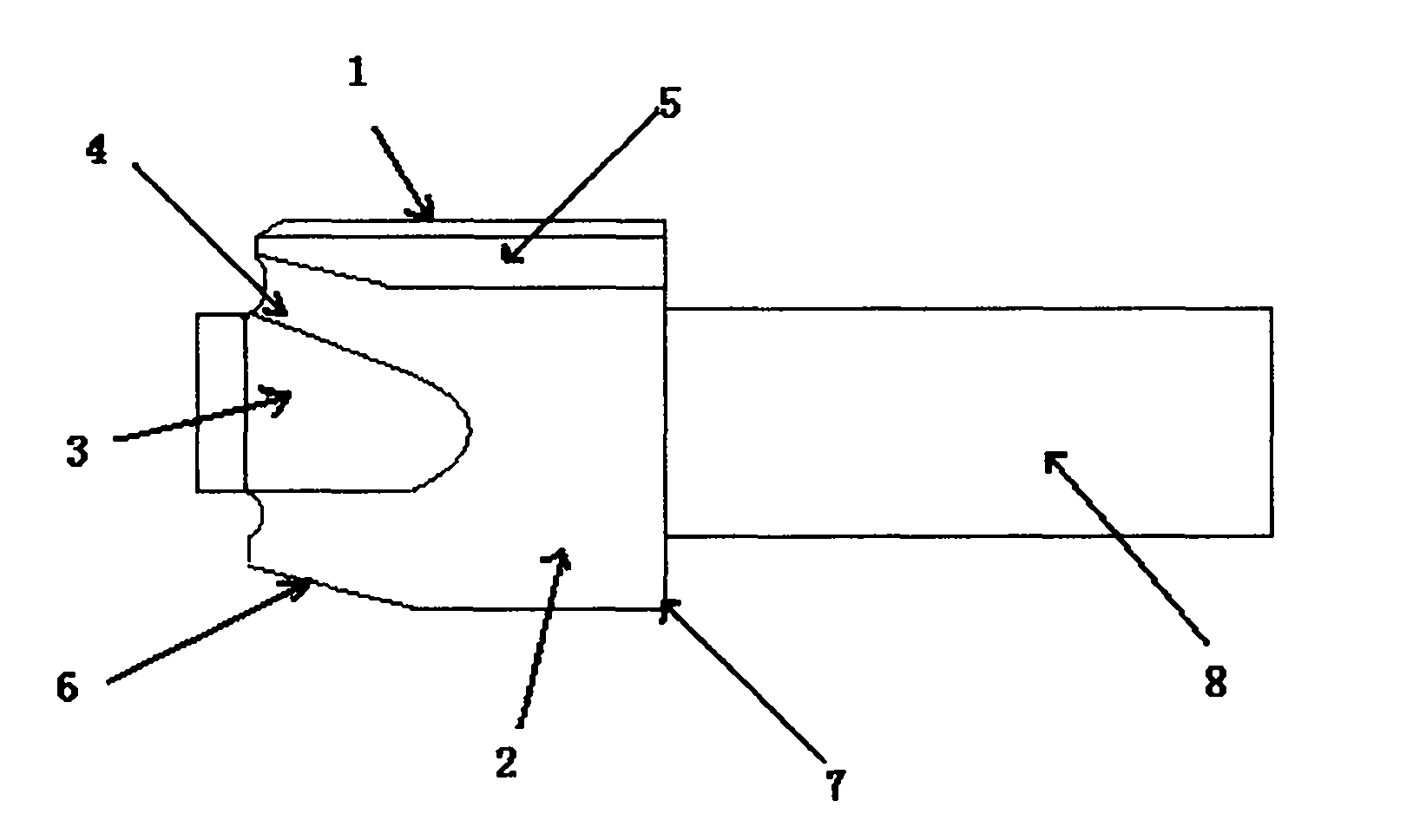
[0003] The purpose of the present invention is to solve the problem of difficult-to-machine materials and the poor rigidity of special-shaped structure tee joints, and the variability of processing and clamping, so as to ensure that the wall thickness of the special-shaped surface is 10 +0.2 The size requirements in mm, the part structure such as figure 1 , 2
Technical solution: reserve a craft chuck in the blank to solve the problem of clamping deformation of the parts, adopt the method of firstly machining the outer surface by CNC milling,...

Method used


Image

  • NC (numerical control) processing method for special-shaped joint part
  • NC (numerical control) processing method for special-shaped joint part
  • NC (numerical control) processing method for special-shaped joint part

Examples


Embodiment 1

[0037] CNC milling:

[0038] Use UG software to create a 3D model of the part with CNC milling and 3232 sequence, follow the steps of rough milling the side walls→rough milling of the upper and lower profiles→semi-finish milling of the upper and lower profiles→fine milling of the side walls→finish milling of the upper and lower planes→finish milling of the upper arc→ Fine milling of the lower arc → fine milling transfer arc → fine milling of the groove → fine milling of the outer wall of the spigot → clearing the root processing route for NC programming, choosing a four-coordinate vertical machining center equipment, and using the process chuck as part positioning And the clamping datum, take the rotation center of the end face of the joint cylinder as the origin of the workpiece coordinates, create a three-dimensional model of the equipment in the UG software, and import it into ~ERICUT simulation software, and create the post-processing file of the equipment according to the ...


PUM


Abstract

The invention provides an NC (numerical control) processing method for a special-shaped joint part. The profile surface of a tee joint is divided into the following parts: a side wall 1, an upper-lower profile 2, an upper-part circular arc 3, a through-connection circular arc 4, a profiled groove 5, a spigot outer wall 6, a root part 7 and a technical chuck 8. The NC processing method is characterized in that: a part blank is adopted to reserve the technical chuck, so as to solve the problem of clamping deformation of the part; the outer profile surface is first processed through NC milling and then the inner profile surface is processed through NC linear cutting. The NC processing method overcomes the disadvantage that the part is difficult to meet the requirement of the special-shaped profile surface for the wall thickness due to having extremely poor rigidity during the processing. The NC processing method in the invention can be applied for manufacturing the special-shaped joint part of a stress application main pipe of a certain machine, and can solve the deformation problem without stress processing.

Description

technical field [0001] The invention relates to some joint parts with complex structures and poor rigidity. Simple structure blanks are used to realize the stress-free processing technology of complex structures, especially for the manufacture of special-shaped joint parts of a machine afterburner main pipe, and to solve the problem of stress-free processing deformation. . Background technique [0002] Since there is no casting material for the special-shaped structure tee joint parts on the afterburner main pipe, and the die forging parting is difficult, and the welding structure is not allowed, the development period is short, and the free forging blank is used to manufacture the part, and ordinary processing and clamping are adopted. method, processing deformation is difficult to control. The specific problem is that according to the design basis, the inner surface is processed first, and then the outer surface is processed. The rigidity of the parts is extremely poor du...

Claims


Application Information

Patent Timeline
IPC IPC(8): B23P15/00
Inventor 魏鉴梅赵昌辉李家永张森棠刘艳张同
Owner SHENYANG LIMING AERO-ENGINE GROUP CORPORATION
Why Eureka
Try Eureka