Method for monitoring pipeline corrosion

A pipeline and pipeline wall technology, applied in the field of sensing, can solve the problems of difficult implementation of detection and maintenance, complex and harsh environmental conditions, and inability to monitor submarine pipelines, so as to meet the needs of long-term stable monitoring and measure long-term stability and reliability. , the effect of improving the overall economic benefits

Inactive Publication Date: 2010-07-07
DALIAN UNIV OF TECH
View PDF0 Cites 48 Cited by
  • Summary
  • Abstract
  • Description
  • Claims
  • Application Information

AI Technical Summary

Problems solved by technology

[0004] Submarine pipelines are generally located in the sea with a water depth of tens of meters or even hundreds of meters. The environmental conditions are complex and harsh, and routine inspection and maintenance are difficult to implement
Existing submarine pipeline corrosion detection methods such as magnetic flux leakage testing, eddy current testing, ultrasonic testing, intelligent pigging balls, underwater robots, etc. have played a very important role in improving the safety of submarine pipelines, but these methods are common and cannot be used on the seabed. Insufficient real-time monitoring of pipeline safety leaves hidden dangers for submarine pipeline damage
Moreover, with the development of offshore oil development to the far sea and deep sea, more and more long-distance submarine pipelines are used. Using these existing detection methods to detect submarine pipelines will take a long time and the efficiency is very low. Therefore, it is necessary to research and develop new types of pipelines. Pipeline Corrosion Monitoring Technology

Method used


Image

  • Method for monitoring pipeline corrosion
  • Method for monitoring pipeline corrosion
  • Method for monitoring pipeline corrosion

Examples


Embodiment Construction

[0020] The specific embodiments of the present invention will be described in detail below in conjunction with the technical solutions and accompanying drawings.

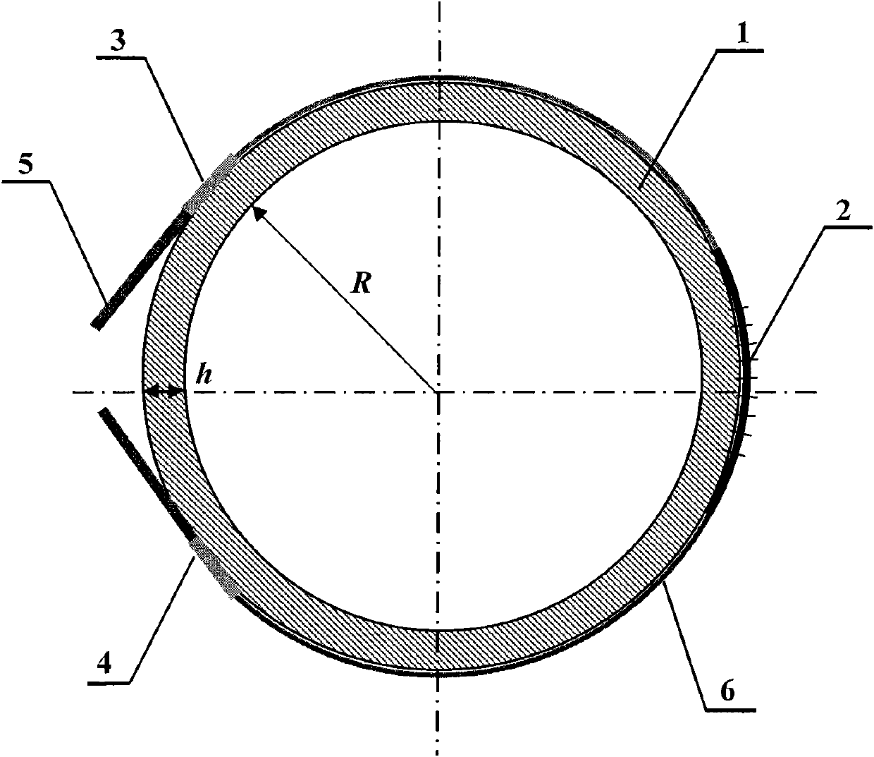
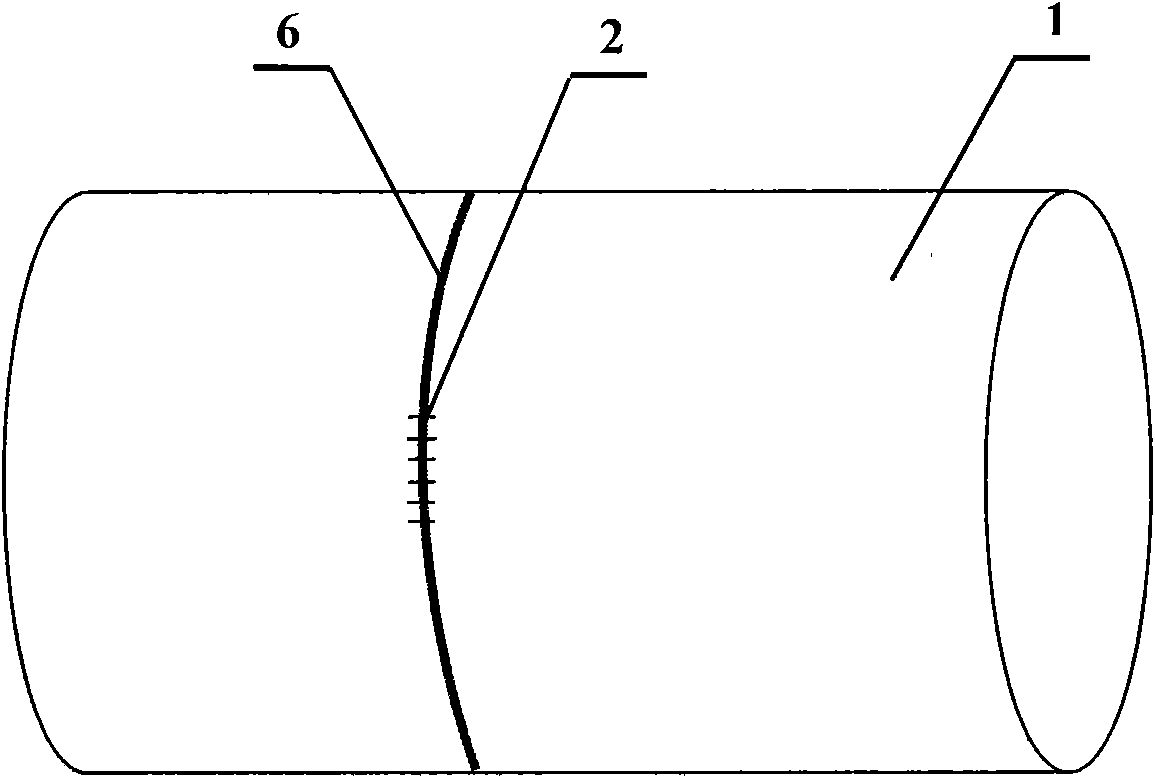
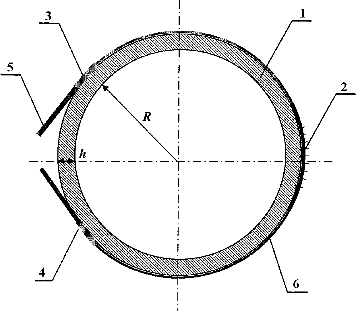
[0021] A schematic diagram of a method for monitoring pipeline corrosion proposed by the present invention is attached figure 1 And attached figure 2 shown. The specific process of fiber grating 2 installation method is:

[0022] Step 1: In order to ensure full contact between the fiber grating 2 and the outer wall of the pipe 1 and avoid measurement errors caused by strain transfer, first use a grinder to polish the outer wall surface of the pipe 1 to remove the paint layer, and then sand it with sandpaper to make the outer wall surface of the pipe 1 Flat and smooth. In order to prevent the impact of sanding dust, oil and other pollutants, use absorbent cotton balls dipped in absolute alcohol to scrub the sanding area.

[0023] Step 2: Paste the fiber bonding point A3 and the fiber bonding point B4 on the surf...


PUM


Abstract

The invention discloses a method for monitoring pipeline corrosion, belonging to the technical field of sensing. The method is characterized by comprising a pipeline wall thickness and pipeline outer wall radial strain relational expression and the installation method of a fiber bragg grating sensor. Because the internal pressure of the pipeline is constant fundamentally, internal and external corrosion of the pipeline decreases the pipeline wall thickness and increases the radial strain of the outer wall of the pipeline. The method can obtain the wall thickness variation condition by monitoring the variation condition of the radial strain of the pipeline for a long term so as to obtain the corrosion degree borne by the measured pipeline. The invention has the effect and benefit that the method for monitoring pipeline corrosion has the advantages of simple principle, convenient installation and no damage to pipeline structure, can realize long-distance real-time on-line measurement and can realize on-line real-time corrosion condition monitoring of the pipeline structure.

Description

technical field [0001] The invention belongs to the field of sensor technology and relates to a method for monitoring pipeline corrosion. Background technique [0002] Some of the submarine oil and gas gathering and long-distance pipelines that have been built in my country have been in service for more than 10 years. These pipelines will inevitably produce various damages during their service, such as internal medium corrosion, external seawater corrosion, stress corrosion and corrosion fatigue under the combined action of internal pressure and other external loads, third-party mechanical damage, and natural damage such as typhoons and ocean currents. Fatigue cumulative damage caused by pipeline vibration caused by environmental loads, etc. These factors will directly affect the service life of submarine pipelines. According to statistics, 47% of submarine pipeline accidents are caused by corrosion and aging of submarine pipelines. Therefore, real-time monitoring of the c...

Claims


Application Information

Patent Timeline
Patent Type & Authority Applications(China)
IPC IPC(8): F17D5/00
Inventor 任亮李宏男孙丽
Owner DALIAN UNIV OF TECH
Why Eureka
Try Eureka