Voltage endurance tester

A technology of withstand voltage tester and tester, which is applied in the direction of testing dielectric strength, etc.

Inactive Publication Date: 2010-07-07
SUZHOU INDAL PARK TAIGE ELECTRONICS SCI &TECH
View PDF0 Cites 6 Cited by
  • Summary
  • Abstract
  • Description
  • Claims
  • Application Information

AI Technical Summary

Problems solved by technology

[0007] In this way, when there is only one electric starting switch 3, it can effectively avoid the harm to the human body due to misoperation, and effectively solve the problem of operation safety

Method used


Image

  • Voltage endurance tester
  • Voltage endurance tester
  • Voltage endurance tester

Examples


Embodiment Construction

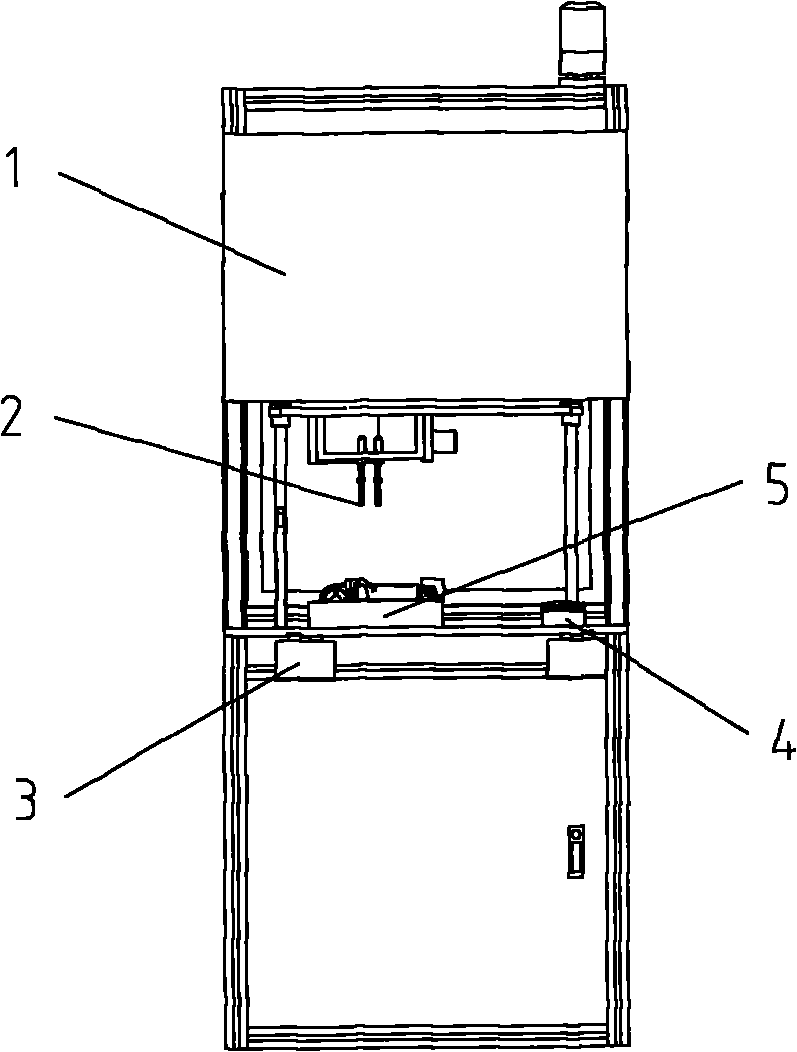
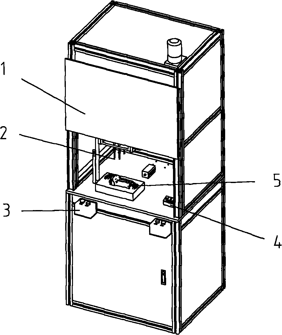
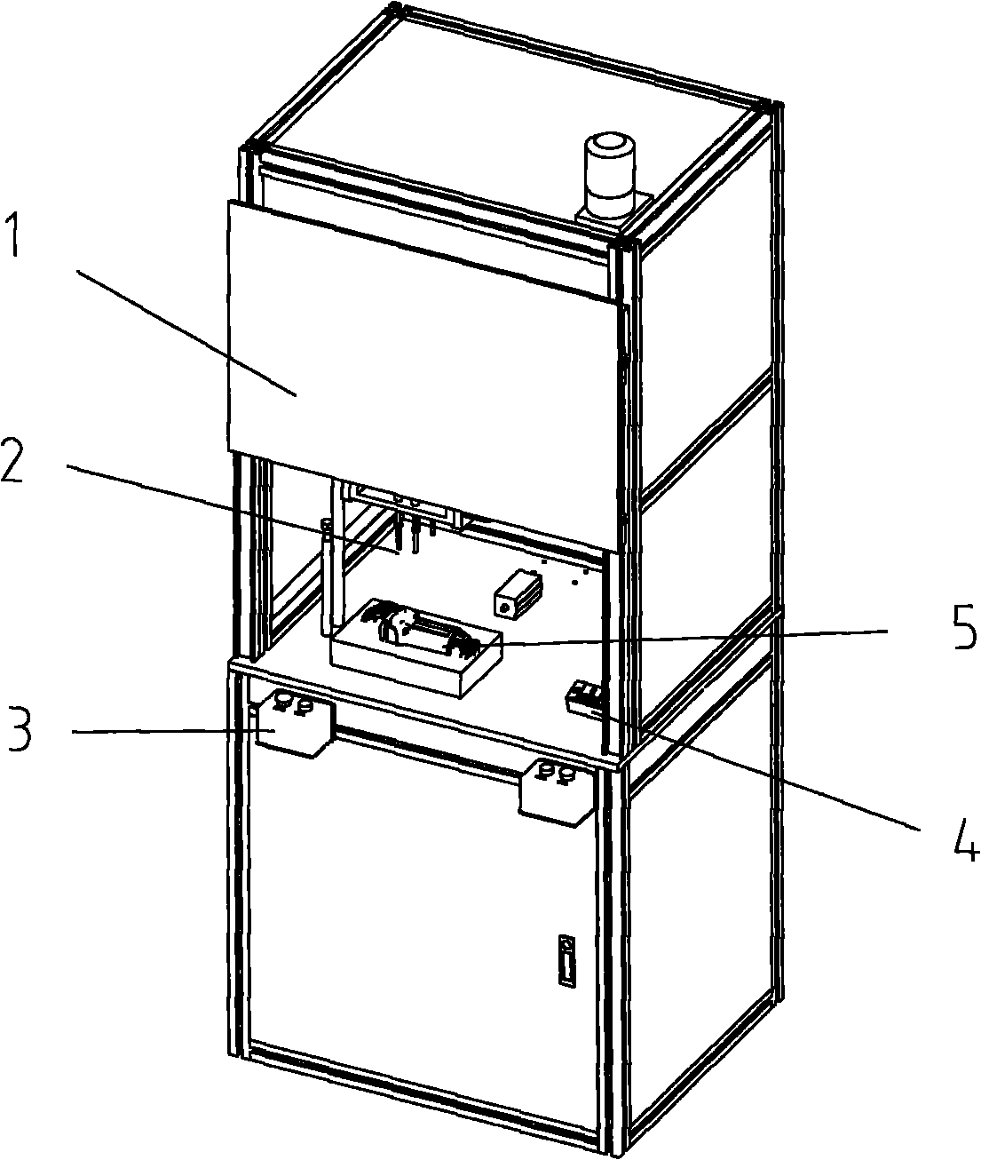
[0010] Combine below Figure 1-2 The withstand voltage tester in the present invention will be described in detail.

[0011] The withstand voltage tester includes a contact 2 and an electric start switch 3; the contact 2 can move under the action of a driving device to contact or leave the metal screw on the shell of the product to be tested 5; preferably, the driving The device may be a cylinder or a lead screw driven by a stepping motor; the electric start switch 3 is used to start the withstand voltage test of the product to be tested.

[0012] The withstand voltage tester also includes a frame, the frame is formed as a closed space, and is equipped with a dodge door, and the dodge door plays a role of safety protection, preferably, the dodge door can be transparent, so that The operator can observe the testing process at any time.

[0013] Preferably, there are two electric start switches 3, which are respectively arranged on the left and right sides of the outside of th...


PUM


Abstract

The invention relates to a voltage endurance tester comprising a contact (2) and electric starting switches (3). The contact (2) is used for applying testing voltage on a shell of a product (5) to be tested. The voltage endurance tester is characterized in that output signals of the two switches (3) are connected to the input end of a starting control signal of the tester by an AND gate. The voltage endurance tester not only can effectively avoid injury to a human body owing to misoperation when only one electric starting switch (3) is started, but also can effectively solve the problem of the operating safety.

Description

technical field [0001] The invention relates to a withstand voltage tester. Background technique [0002] The withstand voltage tester is also called the electrical insulation strength tester or the dielectric strength tester. It is a test that stipulates that AC or DC high voltage is applied between the live part and the non-live part (usually the shell) of the electrical appliance to check the withstand voltage capability of the insulating material of the electrical appliance. [0003] In the long-term operation of electrical appliances, they must not only withstand the rated working voltage, but also withstand the short-term overvoltage that is higher than the rated working voltage during operation (the overvoltage value may be several times higher than the rated working voltage value) . Under the action of these voltages, the internal structure of the electrical insulating material will change. When the overvoltage intensity reaches a certain value, the insulation of ...

Claims


Application Information

Patent Timeline
Patent Type & Authority Applications(China)
IPC IPC(8): G01R31/12
Inventor 严小斌薛振江张鑫
Owner SUZHOU INDAL PARK TAIGE ELECTRONICS SCI &TECH
Why Eureka
Try Eureka