Device capable of automatically adjusting input source of driver

A technology of input power supply and automatic adjustment, applied in output power conversion devices, adjusting electrical variables, data processing power supplies, etc., can solve the problems of lack of elasticity, driving loss, and inability to change the voltage source of the driver, so as to solve the problem of power waste and reduce power consumption. Drive Loss, Effect of Optimizing Efficiency

Active Publication Date: 2013-04-10
ASUSTEK COMPUTER INC
View PDF0 Cites 0 Cited by
  • Summary
  • Abstract
  • Description
  • Claims
  • Application Information

AI Technical Summary

Problems solved by technology

Therefore, the traditional way of supplying power with a fixed voltage source is inflexible, and the voltage source of the drive cannot be changed no matter the system is under light load or heavy load, and unnecessary drive loss will be caused.

Method used


Image

  • Device capable of automatically adjusting input source of driver
  • Device capable of automatically adjusting input source of driver
  • Device capable of automatically adjusting input source of driver

Examples


Embodiment Construction

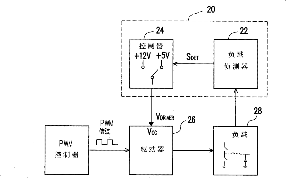
[0020] figure 2 Shown is a circuit block diagram of an apparatus for automatically adjusting the input power of a driver according to an embodiment of the present invention. Please refer to figure 2 , the device 20 for automatically adjusting the input power of a driver may include a load detector 22 and a controller 24 . The load detector 22 detects the usage of the load 28 on the motherboard, and reacts the detected current into a voltage signal. That is, the detection signal S is output according to the change of the load current DET . The voltage signal output by the load detector 22 is proportional to the detected current. The controller 24 is coupled to the load detector 22 and receives the detection signal S DET . The controller 24 according to the detection signal S DET to provide an operating voltage V between the first voltage (+5V) and the second voltage (+12V) DRIVER . automatically adjusts the input power supply device 20 to operate on the voltage V DR...


PUM


Abstract

The present invention relates to a device capable of automatically adjusting an input source of a driver, which comprises a load detector and a controller, wherein the load detector is used for detecting load current and outputting a detecting signal according to the load current; the controller is coupled with the load detector, and is used for receiving the detecting signal; and the controller provides operation voltage between first voltage and second voltage according to the load current, and the first voltage is smaller than the second voltage. The operation voltage is used for providingto the driver, and is elastically adjusted according to different load requirements. The device capable of automatically adjusting an input source of a driver can improve the use efficiency of electricity in light loading.

Description

technical field [0001] The invention relates to a technology for saving power and energy, and in particular to a device for automatically adjusting the input power of a driver. Background technique [0002] Since the issue of energy saving has been paid more and more attention, how to reduce the loss in the process of power conversion to increase the power conversion efficiency has become one of the active research directions of various manufacturers. [0003] figure 1 Shown is a block diagram for supplying the driver with a fixed voltage source. See figure 1 . Traditionally, the power input terminal V provided to the driver (driver) CC The voltage is a fixed voltage source. The voltage source for this driver may be 5 volts or 12 volts. A fixed voltage source is supplied directly to the driver to drive the central microprocessor (CPU) on the motherboard. However, when a general user uses a computer, the CPU is in a light-loaded state for a long time, and the CPU is in...

Claims


Application Information

Patent Timeline
IPC IPC(8): G06F1/32G05F1/10H02M3/155
Inventor 萧贺璞黄农哲许志琬
Owner ASUSTEK COMPUTER INC
Why Eureka
Try Eureka