Design method of production flow

A technology for calculating regions and molecules, applied in calculations, special data processing applications, instruments, etc., can solve the problems of less information, unfavorable assembly process traceability and quality control, document distribution and production management errors, etc., and achieve the effect of simple use

Inactive Publication Date: 2010-07-07
BEIJING INST OF SPACECRAFT ENVIRONMENT ENG
View PDF0 Cites 14 Cited by
  • Summary
  • Abstract
  • Description
  • Claims
  • Application Information

AI Technical Summary

Problems solved by technology

[0003] (1) The amount of information contained is relatively small, which cannot effectively reflect data such as material flow and production feedback;
[0004] (2) The assembly process and sequence cannot be displayed intuitively, providing clear and definite production guidance for process management and operators;
[0005] (3) The process data is relatively scattered. For users, the degree of visualization is not high. Managers and operators cannot quickly check the data

Method used


Image

  • Design method of production flow
  • Design method of production flow
  • Design method of production flow

Examples


Embodiment Construction

[0021] First of all, define the specific functions that the present invention completes:

[0022] a. Save the flow chart: save it to the database after completing the flow chart;

[0023] b. Export flow chart: export the flow chart in picture format;

[0024] c. Abandon the currently drawn flowchart: abandon the currently drawn flowchart;

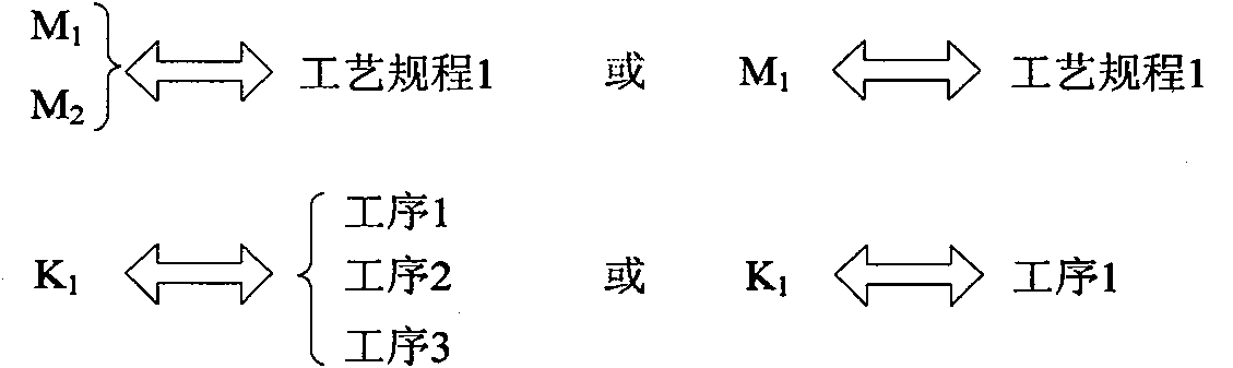
[0025] d. Connecting sub-volumes: connecting between sub-volumes;

[0026] e. Delete sub-volumes or connecting lines: delete sub-volumes or connecting lines in the flowchart;

[0027] f. Insert a tag: Insert a "production process" tag in the flowchart.

[0028] The implementation method is as follows:

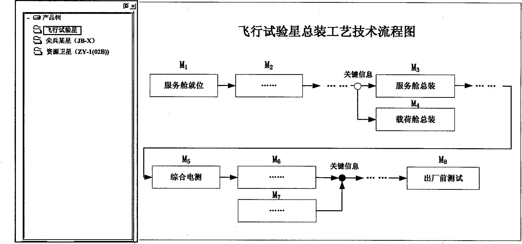
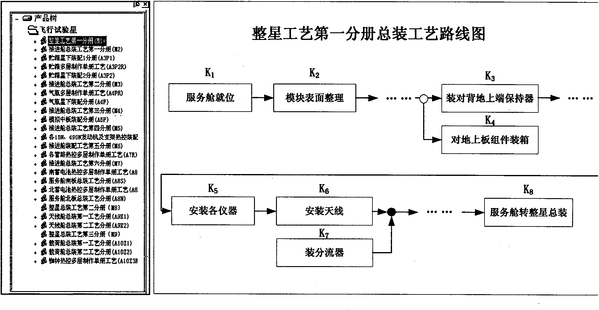
[0029] a. How to draw graphics

[0030] Provides basic geometry tools for drawing flowcharts (analog visio). By dragging and dropping, the drawing of a simple flow chart can be realized. There are two types of diagrams to be drawn here: the technical flow chart of the assembly process and the roadmap of the assembly process. The tech...


PUM


Abstract

The invention relates to a design method of a production flow. In the method, a final assembly (FA) process technique flowchart is drawn: firstly, selecting that the FA process technique flowchart of which spacecraft needs to be generated under a product tree, wherein the FA process technique flowchart comprises parallel operation nodes (M3, M4) and key nodes (M6, M7), and the next node is drawn after the key nodes (M6, M7) are finished; an FA process route chart is drawn: firstly, selecting to generate a process route chart of the FA process, wherein the process route chart comprises parallel operation nodes (K3, K4) and key nodes (K6, K7), the next node is drawn after the key nodes (K6, K7) are finished, the meeting position of arrows of parallel nodes is represented by a hollow or solid circle, and a numeric ordinal (K1) is generated automatically after a geometric figure is increased at one time; the incidence relation between the nodes in a graph is defined: establishing the congruent relationship M-K of the node M in the process flowchart and the node K in the process route chart and adding the corresponding process and the nodes K in the corresponding process in each pixel in the graph after drawing the FA process technique flowchart; a procedure information K-procedure is added in the process route chart: each node in a procedure route chart does not correspond to each procedure in a procedure list, each node in the process route chart can correspond to a plurality of procedures in the procedure list, but one procedure in the procedure list only belongs to one node in the procedure route chart; graphs are browsed: the graphs are managed by adopting the product tress mode; when one type on a structural tree is selected, the corresponding process technique flowchart can be displayed; sub-nodes in the process technique flowchart form the process route chart, and each pixel in the process route chart can display the corresponding.

Description

technical field [0001] The invention relates to a novel production process (route) design method, in particular to a product assembly process (route) design method. Background technique [0002] Traditionally, enterprises generally use the form of assembly process rules for process design and production guidance. For complex processes such as product assembly, the traditional method of assembly process rules has its own limitations: [0003] (1) The amount of information contained is relatively small, which cannot effectively reflect data such as material flow and production feedback; [0004] (2) The assembly process and sequence cannot be displayed intuitively, providing clear and definite production guidance for process management and operators; [0005] (3) The process data is relatively scattered. For users, the degree of visualization is not high. Managers and operators cannot quickly check the data and content they care about, which may easily cause errors in documen...

Claims


Application Information

Patent Timeline
IPC IPC(8): G06F17/50
Inventor 李曼丽张海英门昱刘玉刚孙刚
Owner BEIJING INST OF SPACECRAFT ENVIRONMENT ENG
Why Eureka
Try Eureka