Method for controlling direct power of grid-connected inverter without non-AC voltage sensor

An AC voltage and power control technology, which is applied in the direction of converting AC power input to DC power output, output power conversion devices, electrical components, etc., can solve the problem of improper selection of the initial value of the integrator, failure of the grid-connected inverter, etc. problem, to achieve the effect of simple algorithm, strong anti-interference ability and fast dynamic response

Inactive Publication Date: 2010-07-07
HARBIN INST OF TECH
View PDF0 Cites 32 Cited by
  • Summary
  • Abstract
  • Description
  • Claims
  • Application Information

AI Technical Summary

Problems solved by technology

[0003] The purpose of the present invention is to provide a direct power control method for a grid-connected inverter without an AC voltage sensor, which solves the problem of improper selecti...

Method used


Image

  • Method for controlling direct power of grid-connected inverter without non-AC voltage sensor
  • Method for controlling direct power of grid-connected inverter without non-AC voltage sensor
  • Method for controlling direct power of grid-connected inverter without non-AC voltage sensor

Examples


specific Embodiment approach 1

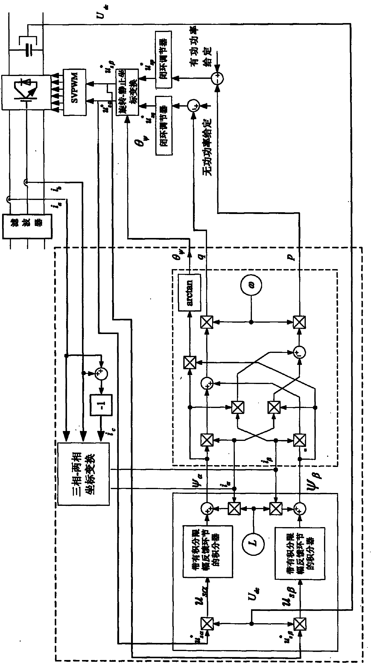
[0012] Specific implementation mode one: the following combination Figure 1 to Figure 3 Describe this embodiment, the control method of this embodiment is:

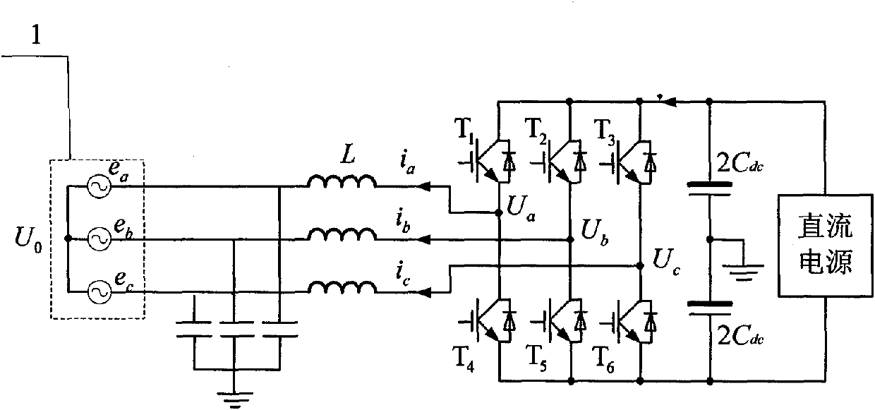
[0013] 1. Connect the filter to the output terminal of the grid-connected inverter to filter the output current, and perform a three-phase-two-phase coordinate transformation on the three-phase current value at the output terminal of the grid-connected inverter to obtain the output value of the grid-connected inverter The component i of the three-phase current value in the two-phase stationary coordinate system α and i β ; Connect the DC capacitor in parallel at the input end of the grid-connected inverter, and set the component u of the given value of the control voltage of the grid-connected inverter in the two-phase stationary coordinate system sα * and u sβ * Respectively with the voltage U across the DC capacitor dc Multiplied together to get the component u of the inverter voltage value of the current grid-co...

specific Embodiment approach 2

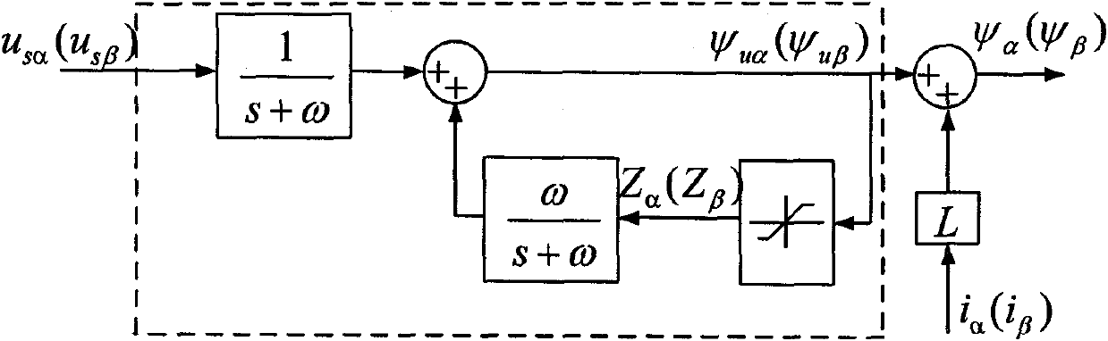
[0034] Specific implementation mode two: the following combination Figure 4 Describe this embodiment. This embodiment is a further description of the calculation of the given values ​​of active power and reactive power of the grid-connected inverter in the first embodiment: the given active power of the grid-connected inverter described in the third value p * It is obtained by the following method: the output voltage U of the DC capacitor dc With a given voltage of the DC capacitor U dc * comparison, and then the obtained comparison result is adjusted by the PI closed-loop regulator, and then the adjusted output value of the PI closed-loop regulator is compared with the output voltage U of the DC capacitor dc Multiply to get active power given value p * . The given value of reactive power of the grid-connected inverter mentioned in 3 is 0.

[0035] This implementation mode adopts a double-closed-loop control structure with a DC capacitor voltage outer loop and a grid-co...


PUM


Abstract

The invention provides a method for controlling direct power of a grid-connected inverter without any non-AC voltage sensor and belongs to the field of electric energy transformation. The invention aims to solve the problem that because an initial value of an integrator in a virtual flux observer of a voltage vector on the network side is improperly selected, the grid-connected inverter cannot normally operate. The method comprises the following steps of: by transformation, obtaining components i alpha and i beta of the three-phase current value in a two-phase stationary coordinate system; by calculation, obtaining components us alpha and us beta of the inversion voltage value of the current grid-connected inverter in the two-phase stationary coordinate system; after the integration of the integrator, calculating components psi alpha and psi beta of the magnetic flux linkage of the voltage on the network side in the two-phase stationary coordinate system; calculating the instantaneous output active power p and reactive power q of the grid-connected inverter, and obtaining components usp * and usq * of the control voltage set value of the new grid-connected inverter in a two-phase rotary coordinate system; and finally obtaining the control signal of all power devices of the grid-connected inverter. The method can be used for direct power control of the grid-connected inverter.

Description

technical field [0001] The invention relates to a direct power control method of a grid-connected inverter without an AC voltage sensor, belonging to the field of electric energy conversion. Background technique [0002] Grid-connected inverter is a key component of renewable energy power generation system, and its control performance directly affects grid-connected power quality and grid-connected efficiency. Most of the existing grid-connected inverter control strategies use direct current control or voltage-oriented vector control. Direct current control has the problem of poor ability to resist grid disturbances, and voltage-oriented vector control requires a large number of control algorithms such as rotational coordinate transformation, which makes the system complex to implement and has high requirements for processor performance. In particular, current inverters using voltage-oriented vector control all use AC voltage sensors to detect the synchronous phase angle of...

Claims


Application Information

Patent Timeline
IPC IPC(8): H02M7/5387
Inventor 吴凤江赵克孙力王有琨
Owner HARBIN INST OF TECH
Why Eureka
Try Eureka