Ejector sleeve ejecting structure in plastic mould slide block

A technology of plastic molds and sliders, applied in the field of plastic molds, can solve the problems of inability to open molds, uneven force at column holes, poor reliability, etc., to prevent plastic products from being pulled, good demoulding effect, and reliability. high effect

Inactive Publication Date: 2010-07-14
宁海县现代模具有限公司
View PDF7 Cites 7 Cited by
  • Summary
  • Abstract
  • Description
  • Claims
  • Application Information

AI Technical Summary

Problems solved by technology

[0002] In the manufacturing process of plastic molds, many times the product has an undercut in the fixed mold direction (the demoulding direction at this position is inconsistent with the mold opening direction), so it cannot be demoulded, and a slider must be used to demould. When the plastic product needs to be produced When the ribs are many and deep, especially if there are deep post holes on the plastic product, the plastic product will easily stick to the slider when the mold is opened, resulting in failure to open the mold or even straining the product.
[0003] In order to solve the above problems, it is difficult to directly install the cylinder in the slider to push the slider out of the column hole. The demoulding and ejection structure at the column hole in the prior art includes an inclined guide column, a locking block, a slider , thimble, the slanted guide post is fixed in the locking block, the slanted guide post passes through the slider obliquely, the thimble is arranged on the slider next to the post hole, but two thimbles are designed next to the post hole The way to realize the demoulding of the product has poor reliability, and because of the uneven force on the post hole, the product will appear white (that is, the place where the thimble is pushed is white), so the demoulding effect is not ideal.

Method used


Image

  • Ejector sleeve ejecting structure in plastic mould slide block
  • Ejector sleeve ejecting structure in plastic mould slide block
  • Ejector sleeve ejecting structure in plastic mould slide block

Examples


Embodiment Construction

[0014] The present invention will be further described below in conjunction with the accompanying drawings and specific embodiments.

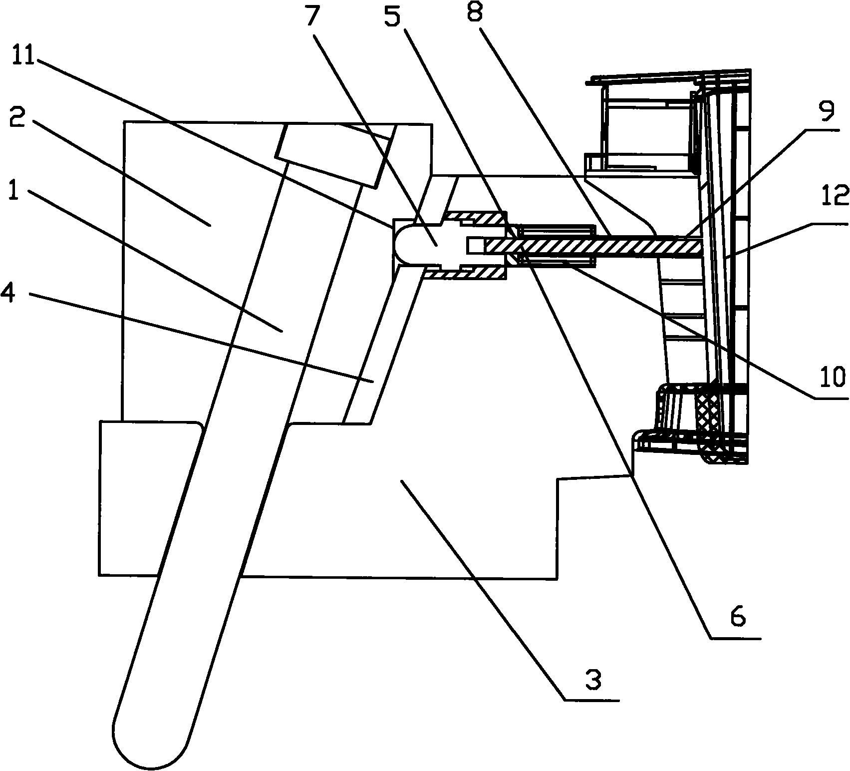
[0015] The cylinder ejection structure in the plastic mold slider of the present invention includes an oblique guide post 1, a locking block 2, and a slider 3. The oblique guide post 1 is obliquely fixed in the locking block 2, and the oblique guide post 1 Pass through the slider 3 obliquely, the right side of the locking block 2 is an inclined surface, the lower end of the slider 3 is close to the locking block 2, and the upper end of the slider 3 passes through the wear-resistant block 4 and The right sides of the locking block 2 are close together.

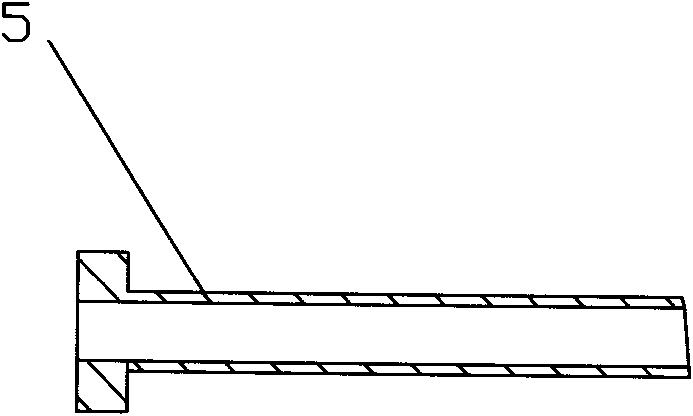
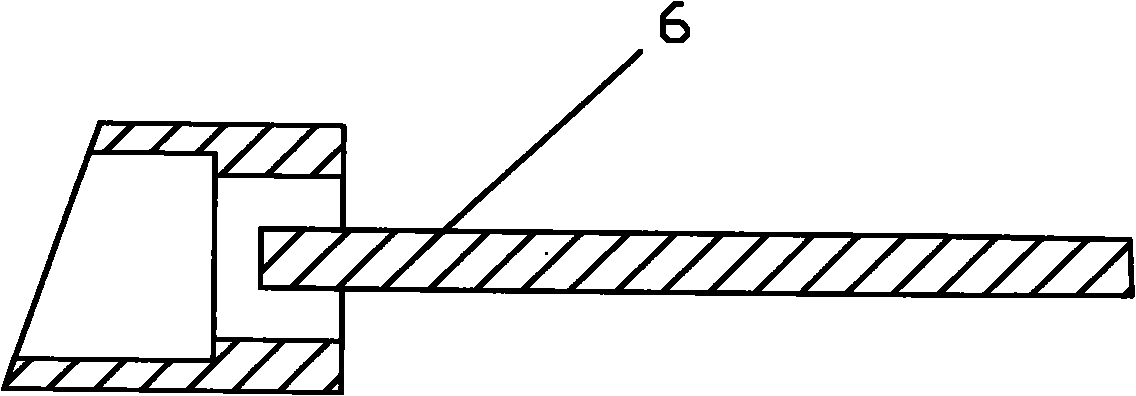
[0016] The ejecting structure of the cylinder also includes a cylinder 5, an insert 6, and a top block 7. A cylinder installation hole 8 is provided in the middle of the slider 3, and the cylinder 5 passes through the cylinder in the slider 3. The barrel installation hole 8 is against the produ...


PUM


Abstract

The invention discloses an ejector sleeve ejecting structure in a plastic mould slide block. The ejector sleeve ejecting structure comprises an inclined guide column (1), a locking block (2), the slide block (3), an ejector sleeve (5), an insert pin (6) and a jacking block (7), wherein an ejector sleeve mounting hole (8) is formed in the slide block (3); the ejector sleeve (5) passes through the ejector sleeve mounting hole (8) in the slide block (3) and is pressed against a product column hole (9), and the outer side of the ejector sleeve (5) is also sleeved with a spring (10); the insert pin (6) is arranged in the ejector sleeve and pressed by a wear plate (4); the right side surface of the locking block (2) is provided with a vertical sliding surface (11); and the right end of the jacking block (7) is sleeved into the tail part of the insert pin (6), and the left end of the jacking block (7) passes through the wear plate block (4) and is pressed against the vertical sliding surfaceof the locking block. The ejector sleeve ejecting structure has the advantages of effectively avoiding the strain of a plastic product and an ejector mark, along with good demolding effect and high reliability.

Description

technical field [0001] The invention relates to the field of plastic molds, in particular to a cylinder ejection structure in a plastic mold slider. Background technique [0002] In the manufacturing process of plastic molds, many times the product has an undercut in the fixed mold direction (the demoulding direction at this position is inconsistent with the mold opening direction), so it cannot be demoulded, and a slider must be used to demould. When the plastic product needs to be produced When the ribs are many and deep, especially if there are deep post holes on the plastic product, the plastic product will easily stick to the slider when the mold is opened, resulting in failure to open the mold or even straining the product. [0003] In order to solve the above problems, it is difficult to directly install the cylinder in the slider to push the slider out of the column hole. The demoulding and ejection structure at the column hole in the prior art includes an inclined g...

Claims


Application Information

Patent Timeline
Patent Type & Authority Applications(China)
IPC IPC(8): B29C33/44
Inventor 林从盛
Owner 宁海县现代模具有限公司
Why Eureka
Try Eureka