
Automatic marking device of round bar

A round bar, automatic technology, applied in printing, stamping and other directions, can solve the problems of difficult continuous production of stamping equipment, high labor intensity of workers, reduced equipment utilization, etc., to improve safety, work efficiency and improve work efficiency. Effect

Active Publication Date: 2010-07-14
QIFENG PRECISION IND SCI TECH
View PDF0 Cites 8 Cited by
  • Summary
  • Abstract
  • Description
  • Claims
  • Application Information

AI Technical Summary

Problems solved by technology

It can be seen that the current work efficiency of engraving on the round bar is low, and it is difficult for the stamping equipment to achieve continuous production, which reduces the utilization rate of the equipment and increases the production cost; the labor intensity of the workers is high, and the round bars on the stamping equipment are all processed manually. The method of picking and placing; the operation is unsafe, and there are great potential safety hazards for workers in actual operation

Method used


Image

  • Automatic marking device of round bar
  • Automatic marking device of round bar
  • Automatic marking device of round bar

Examples


Embodiment

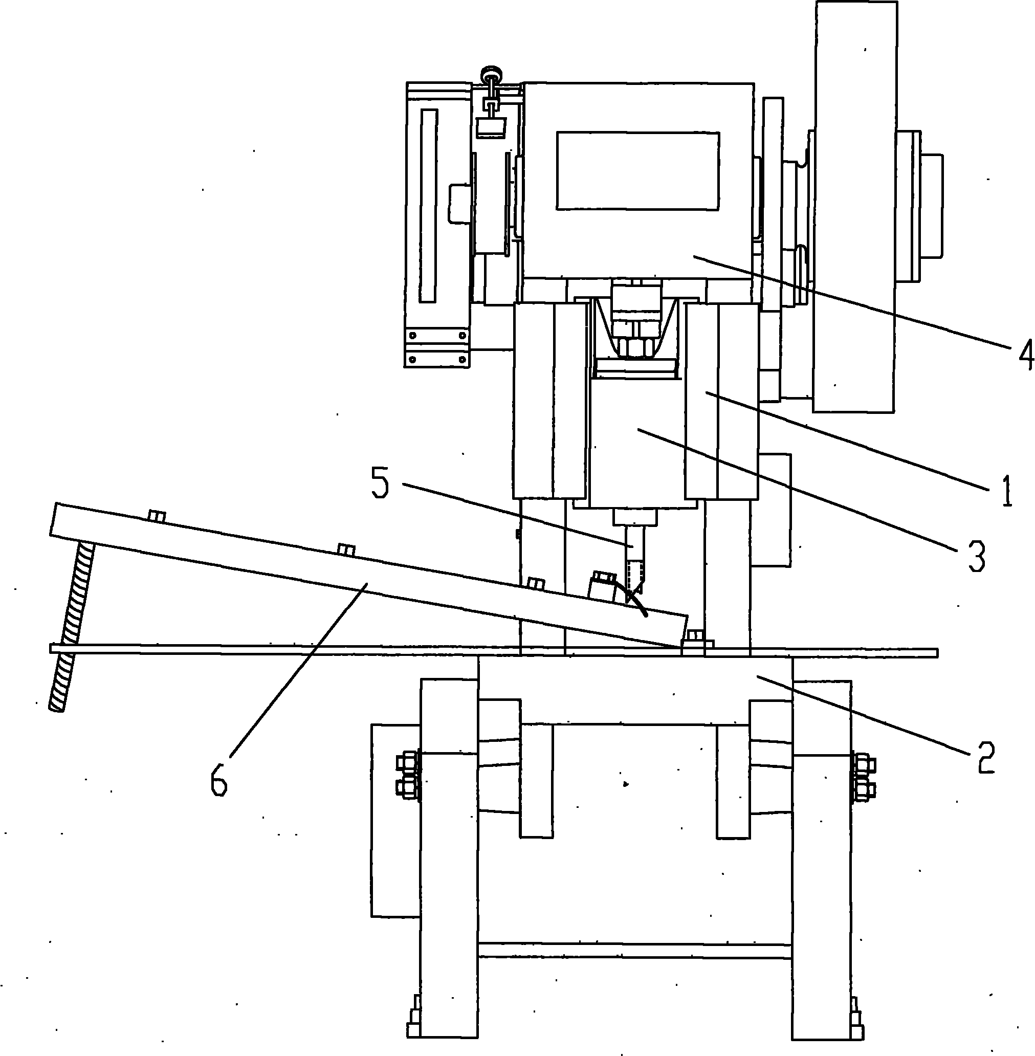
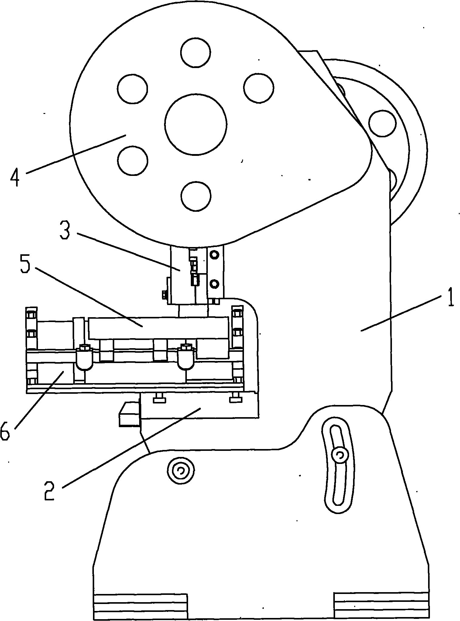
[0026] see Figure 1 to Figure 8 , the round bar marking automatic marking device in this embodiment is made up of stamping equipment, punching die 5 and round bar feeding equipment 6, wherein the stamping equipment includes a frame body 1, a working platform 2 and a transmission mechanism 4 with a stamping block 3, the working platform 2 and the transmission mechanism 4 are installed on the frame body 1, the working platform 2 is horizontal, the working platform 2 is located below the transmission mechanism 4, and the stamping block 3 can punch downward under the action of the transmission mechanism 4. The stamping equipment in the present invention is the same as or similar to the prior art, and will not be described in detail here.

[0027] The punching die 5 in this embodiment has an integrated structure, and the punching die 5 is installed in the punching block 3 of the punching equipment, and the punching block 3 drives the punching die 5 to perform punching downward. D...


PUM


Abstract

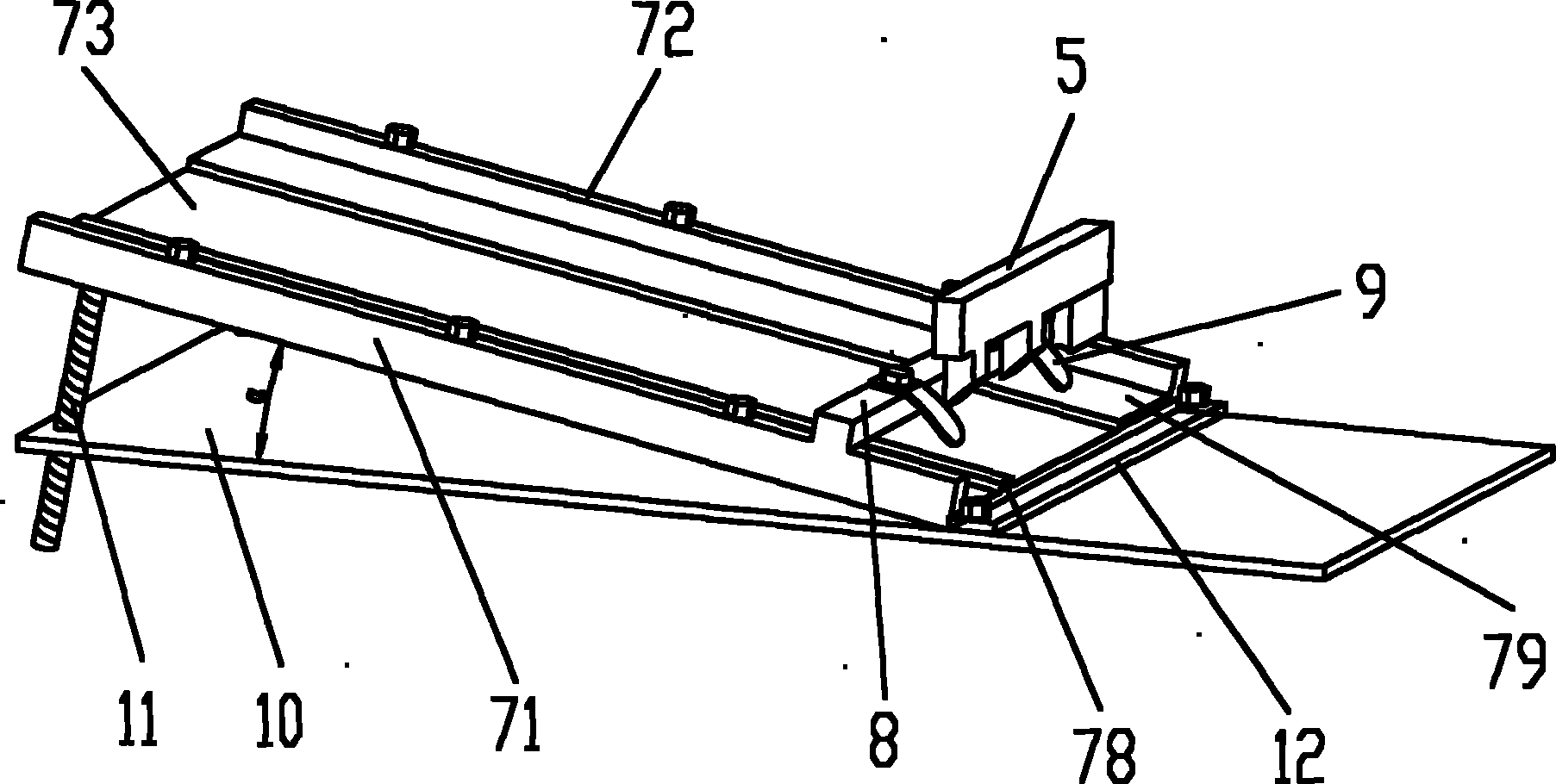
The invention relates to an automatic marking device of a round bar mark. At present, the working efficiency of marking on a round bar is low, and therefore, the continuous production is difficult to realize. The automatic marking device comprises a stamping die and stamping equipment and is characterized by comprising round bar feeder equipment, wherein the round bar feeder equipment comprises a round bar rollaway nest, a beam, a horizontal plate, at least two rollaway nest plates and at least two elastic separation blades, wherein the round bar rollaway nest is arranged on the horizontal plate; the included angle between a bottom plate and the horizontal plate in the round bar rollaway nest is 5 to 30 degrees; both ends of the beam are respectively fixed on a left side baffle and a right side baffle; and the elastic separation blades are fixed on the beam. The stamping die comprises a marking die and at least two wedge-shaped punches, wherein the bottom of the marking die is in a circular arc shape; the bottoms of the wedge-shaped punches are cutting edges; the cutting edges and the circular arc-shaped bottom in the marking die are malposed; the wedge-shaped punches are mutually flush with each other; and the stamping die is arranged above the elastic separation blades. The invention has reasonable structural design and high working efficiency and can automatically mark batch round bar marks.

Description

technical field [0001] The invention relates to an automatic engraving device, in particular to an automatic engraving device for marking round rods, which is mainly used for engraving and marking batches of round rods, and is especially suitable for marking and marking batches of metal round rods. Background technique [0002] The prepared round rods need to be marked by engraving. The existing technology mainly uses manual methods to put the round rods into the stamping equipment one by one for marking and marking. The main steps are as follows: 1. Take a piece manually Put the round bar to be marked and engraved into the stamping equipment; 2. Carry out marking on the round bar through the stamping equipment; 3. Remove the marked round bar from the stamping equipment manually; 4. Manually Take another round rod to be marked and engraved and put it into the stamping equipment for engraving, so the cycle continues. It can be seen that the current work efficiency of engravi...

Claims


Application Information

Patent Timeline
IPC IPC(8): B41K3/04B41K3/62
Inventor 陈跃忠
Owner QIFENG PRECISION IND SCI TECH
Learn More