Air brake valve for locomotive and use method thereof

An air brake valve and locomotive technology, applied to locomotives, brakes, brake components, etc., can solve the problems of not being able to receive the master locomotive, and unable to realize the synchronous action of the slave locomotive

Active Publication Date: 2010-07-14
BEIJING CSR TIMES LOCOMOTIVE & ROLLING STOCK MECHANICS +1
View PDF4 Cites 8 Cited by
  • Summary
  • Abstract
  • Description
  • Claims
  • Application Information

AI Technical Summary

Problems solved by technology

In the existing air brake valve, since there is only one micro switch controlled by the positioning cam, in the four working positions of the air brake valve, at most two electrical signals can only be generated and transmitted to the wireless synchronous control system, so In fact, the wireless s

Method used


Image

  • Air brake valve for locomotive and use method thereof
  • Air brake valve for locomotive and use method thereof
  • Air brake valve for locomotive and use method thereof

Examples


Embodiment Construction

[0034] The following will clearly and completely describe the technical solutions in the embodiments of the present invention with reference to the accompanying drawings in the embodiments of the present invention. Obviously, the described embodiments are only some, not all, embodiments of the present invention. Based on the embodiments of the present invention, all other embodiments obtained by persons of ordinary skill in the art without creative efforts fall within the protection scope of the present invention.

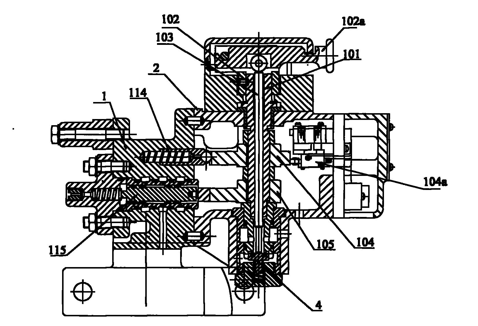
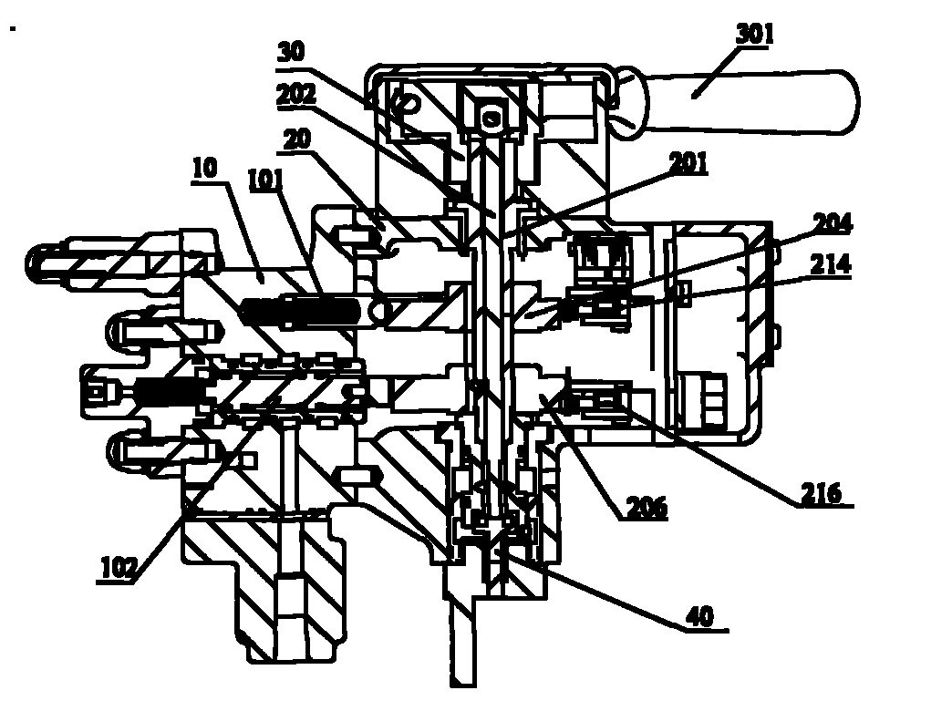
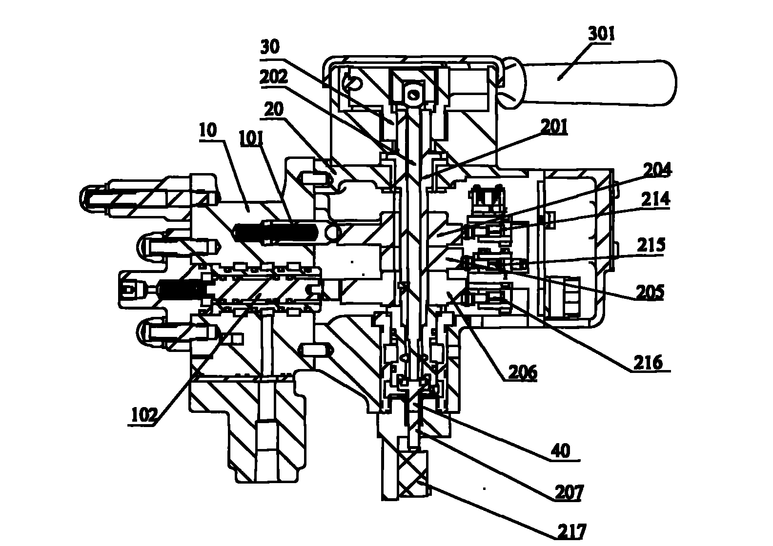
[0035] See figure 2 , is a schematic diagram of the first embodiment of an air brake valve for a locomotive provided by the present invention. Such as figure 2 As shown, the air brake valve for a locomotive includes a valve body 10 and a cam box 20 connected to the valve body 10, an exhaust valve 40 is connected to the lower end of the cam box, and a handle shaft 201 is installed in the cam box. In this embodiment, the cross section of the handle shaft 201 is i...


PUM


Abstract

The invention provides an air brake valve for a locomotive, which is characterized by comprises a valve body, a cam box connected with the valve body, and an air exhaust valve arranged at the bottom of the cam box; a hand shaft is arranged in the cam box, the center of the hand shaft is provided with a mandril, and the hand shaft is sleeved with a first cam and a second cam; an interlock switch group is arranged in the cam box, and the interlock switch group comprises a first micro switch controlled by the first cam, and a second micro switch controlled by the second cam; and a positioning plunger controlled by the first cam and an action plunger controlled by the second cam are arranged in the valve body. Because the first micro switch and the second micro switch can be combined to produce four electric signals corresponding to the release position, the operation position, the neutral position and the brake position of the air brake valve, after the electric signals are transmitted to a computer, the computer can control a driven locomotive according to the four electric signals, so that the driven locomotive keeps synchronous action with a main control locomotive.

Description

technical field [0001] The invention relates to the technical field of brakes, in particular to an air brake valve for a locomotive. Background technique [0002] Electro-pneumatic braking is a commonly used braking form of locomotive braking systems. Taking the DK-1 locomotive electro-pneumatic brake developed in the 1970s in my country as an example, it has the advantages of accurate decompression and fast air charging. , Brake valve control handle is flexible, noise pollution is small, etc., and it is widely used in the braking system of locomotives at present. [0003] In the locomotive electro-pneumatic brake, the air brake valve is its core component. The air brake valve has two working conditions: electric vacant position and air position. In the electric vacant position, the braking, pressure maintenance and release of the locomotive are controlled independently by controlling the pressure of the action chamber. At this time, the air brake valve acts as a "small gate...

Claims


Application Information

Patent Timeline
IPC IPC(8): B60T15/04B61C17/12
Inventor 韩晟
Owner BEIJING CSR TIMES LOCOMOTIVE & ROLLING STOCK MECHANICS
Why Eureka
Try Eureka