
Multilayer imaging screen electric fireplace

An imaging screen and electric fireplace technology, which is applied to household stoves/stoves, electric heating fuels, household heating, etc., can solve the problems of lack of three-dimensional flame multi-layer structure, poor three-dimensional effect, and small depth range, so as to improve the artistic appeal. The effect of strong force, strong stereoscopic effect and large depth range

Inactive Publication Date: 2013-01-23
YIWU ANDONG ELECTRICAL APPLIANCES
View PDF2 Cites 0 Cited by
  • Summary
  • Abstract
  • Description
  • Claims
  • Application Information

AI Technical Summary

Problems solved by technology

[0003] The present invention provides a flame with rich layers, a large depth range and a strong three-dimensional effect in order to solve the problems that the electric fireplace in the prior art has few flame layers, small depth range, lack of multi-layer structure of three-dimensional flame, and poor three-dimensional effect. Multilayer Imaging Screen Electric Fireplace

Method used


Image

  • Multilayer imaging screen electric fireplace
  • Multilayer imaging screen electric fireplace
  • Multilayer imaging screen electric fireplace

Examples


Embodiment 1

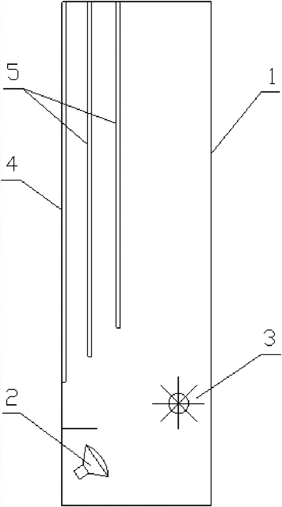
[0021] in such as figure 1 In the shown embodiment 1, a multi-layer imaging screen electric fireplace includes a housing 1, an imaging light source 2, a light processing device 3 and an imaging screen. The light transmittance of the imaging screen is 65%, and the light reflection rate is 35%. The imaging screen includes a main imaging screen 4 and two auxiliary imaging screens 5, the auxiliary imaging screen is arranged on the rear side of the main imaging screen, arranged side by side in the front and back direction of the electric fireplace, the lower end of the auxiliary imaging screen is a suspended structure, close to The bottom of the auxiliary imaging screen of the main imaging screen is lower than the auxiliary imaging screen away from the main imaging screen, the imaging light source is arranged on the front side of the electric fireplace shell, and the light processing device is arranged on the lower side of the electric fireplace shell close to the rear wall.

Embodiment 2

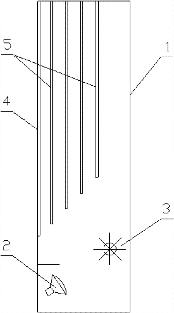
[0023] in such as figure 2 In the shown embodiment 2, the imaging screen includes a main imaging screen and 4 secondary imaging screens, the light transmittance of the imaging screen is 55%, and the light reflection rate is 45%. The imaging screens are arranged in parallel and at equal intervals. The connecting line at the lower end forms an angle of 45 degrees with the horizontal plane, and the secondary imaging screen near the main imaging screen is provided with a flame-shaped molding hole 6 (see Figure 5 ), and the rest are the same as in Example 1.

Embodiment 3

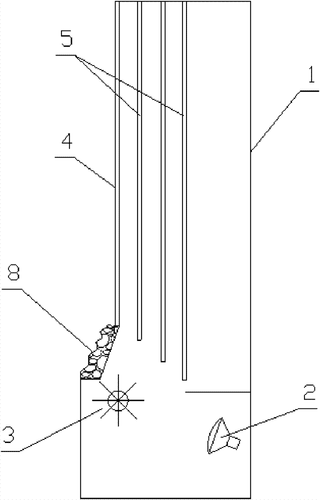
[0025] in such as image 3 In the shown embodiment 3, the imaging screen includes a main imaging screen and 3 secondary imaging screens, the light transmittance of the imaging screen is 50%, the light reflection rate is 50%, and the bottom position of the secondary imaging screen close to the main imaging screen is high. on the secondary imaging screen that is far away from the main imaging screen. The light processing device is arranged on the front side of the electric fireplace shell, the imaging light source is arranged on the lower side of the electric fireplace shell close to the rear wall, and the simulated charcoal bed 8 is arranged under the front side of the main imaging screen, and the rest are the same as in Embodiment 1.


PUM


Abstract

The invention discloses a multilayer imaging screen electric fireplace which comprises a shell, an imaging light source, a ray-processing device and an imaging screen. The imaging screen comprises a main imaging screen and at least two auxiliary imaging screens, wherein the auxiliary imaging screens are arranged behind the main imaging screen and arranged side by side in the fore-and-after direction of the main imaging screen, and the lower end of either auxiliary imaging screen is in a suspension structure. The invention effectively solves the problems of small levels and small depth range of flames, absence of three-dimensional flames in a multilayer structure and poor three-dimensional effect of the electric fireplace in the prior art. The invention overlaps simulated flames on a plurality of imaging screens to form a flame image with rich layers, great depth and strong three-dimensional sense, remarkably improves the flame simulation effect of the electric fireplace and greatly improves the art infectivity of the electric fireplace.

Description

technical field [0001] The invention relates to a simulated fireplace, in particular to a multi-layer imaging screen electric fireplace with rich flame layers, large depth range and strong three-dimensional effect. Background technique [0002] In the prior art electric fireplace, the light processing device is usually used to reflect the light of the imaging light source to the imaging screen to simulate the flame of the fireplace. The flame has a single-layer structure and has a small visual depth range and poor three-dimensional effect. The patent document with publication date of November 11, 2009 and publication number CN101576273 discloses a multi-layer flame electric fireplace with internal and external imaging screens, including a shell, a heating device on the shell, an imaging light source, and an imaging light source. The light processing device above, the simulated carbon bed and the imaging screen close to the simulated carbon bed, the imaging screen includes an...

Claims


Application Information

Patent Timeline
Patent Type & Authority Patents(China)
IPC IPC(8): F24C7/00F24C15/06G02B17/06
Inventor 朱宏锋
Owner YIWU ANDONG ELECTRICAL APPLIANCES
Learn More