Trunnion-free grip-holder used for forge

A technology for forging and hinge shafts, which is applied in the direction of manufacturing tools, forging/pressing/hammer devices, forging/pressing/hammering machinery, etc. It can solve problems such as chucks protruding into the furnace, short moment of arm, and shell tearing. , to achieve the effects of low manufacturing cost, accurate position of picking and placing blanks, and large clamping force

Inactive Publication Date: 2005-05-25
蒋志高
View PDF1 Cites 0 Cited by
  • Summary
  • Abstract
  • Description
  • Claims
  • Application Information

AI Technical Summary

Problems solved by technology

[0007] The technical problem to be solved by the present invention is to overcome the short moment of the force arm of the prior art clamping the billet, and the small moment of the clamping jaw can not be extended, so that the chuck is easy to burn out when it is inserted into the furnace, and the overthrust of the pull rod Disadvantage of tearing the shell apart, providing a hingeless chuck for forging

Method used


Image

  • Trunnion-free grip-holder used for forge
  • Trunnion-free grip-holder used for forge
  • Trunnion-free grip-holder used for forge

Examples


Embodiment Construction

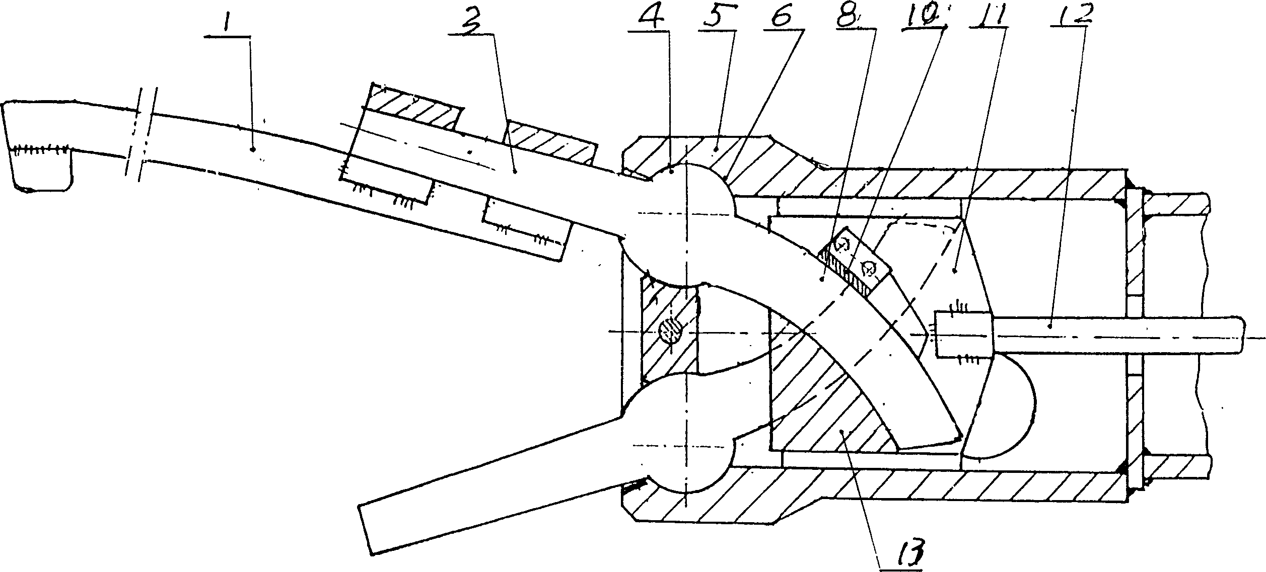
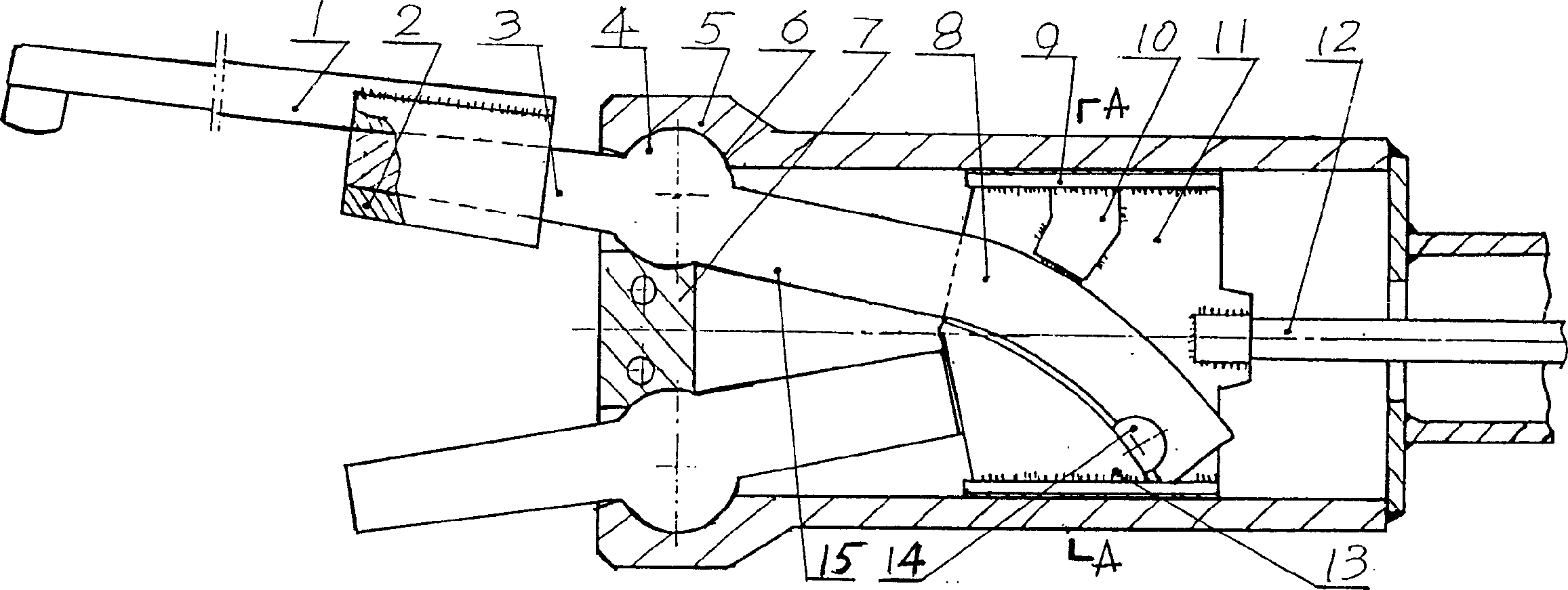
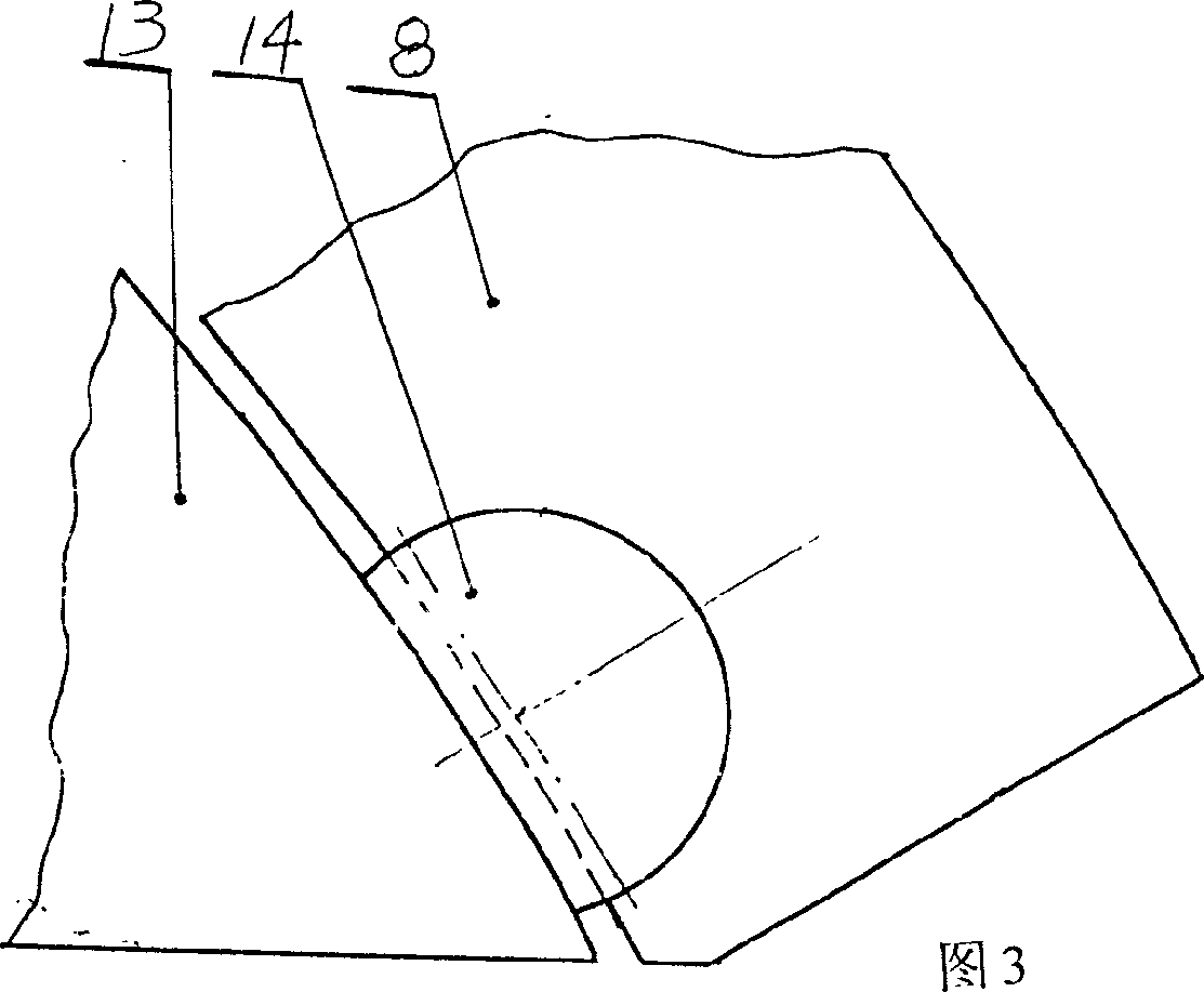
[0027] figure 1 It is a collet in the prior art. In the collet shell 5, there are two gripper bodies with shanks interlaced and inserted into the shell 5. The gripper arm 3 at the left end of the gripper body extends out of the shell 5, and the end is installed with The front jaw 1; the up and down movement of the two front jaws 1 to clamp the blank is achieved by the cooperation of the cylinder 4 in the middle of the respective jaw arm 3 and the arc handle 8 and the concave cylindrical surface 6 on the left wall of the shell 5. Realized, the handles of the upper and lower jaw bodies are arc-shaped handles 8 that are relatively curved upward and downward from the right side of the cylinder 4; 11. The wedge-shaped block 13 fixed at its lower part faces the inner curved surface of the arc-shaped handle 8, and the pull plate 11 on the top surface of the arc-shaped handle 8 is fixed with a guide block 10 guiding the arc-shaped handle 8, and the rear part of the pull plate 11 is pu...


PUM


Abstract

A clamper without hinging axle for forging is composed of casing, two clamping jaws with arc handles which are mutually crossed and the cylindrical bodies arranged between said clamping jaw and arc handle, an axially sliding pull plate between the crossed arc handles, and the guide block and wedge block fixed at upper and lower sides of said pull plate. Its advantages are long clamping jaw and handle for high clamping force moment, not burning off the clamper, and not tearing off the casing.

Description

technical field [0001] The invention belongs to tools, in particular to a chuck for a manipulator used for loading or unloading a sintering furnace when blanks are forged and heated. Background technique [0002] Forging the workpiece on the forging machine, the blank used is put into the furnace to be heated and taken, which is generally realized by the chuck with jaws installed on the manipulator. The patent number is 91211891.1, and the name is "Hingeless Shaft Chuck for Forging Heating" figure 1 The shown chuck includes a housing 5 and two arc-shaped handles 8 mounted therein that are staggered and relatively inwardly curved, and connected with the jaw arms 3 protruding from the housing 5 . Between the jaw arm 3 and the arc handle 8 is connected a cylinder 4 with upper and lower outer arc surfaces, which is installed in the concave arc surface 6 on the housing wall, and the jaw arm 3 extends out of the end of the shell 5 The front jaw 1 is installed on the front part; ...

Claims


Application Information

Patent Timeline
Patent Type & Authority Applications(China)
IPC IPC(8): B21J13/10
Inventor 蒋志高
Owner 蒋志高
Why Eureka
Try Eureka