Surface pasting type vibration wire type reinforcing steel strain gauge

A strain gauge and vibrating wire technology, which is applied in the field of civil engineering testing instruments, can solve the problems of complex installation, lower measurement accuracy, and errors, and achieve the effects of simple structure, convenient use, and low cost

Active Publication Date: 2012-06-06
UNIV OF SCI & TECH BEIJING
View PDF0 Cites 0 Cited by
  • Summary
  • Abstract
  • Description
  • Claims
  • Application Information

AI Technical Summary

Problems solved by technology

[0003] (1) The shape of the traditional steel bar strain gauge (stress gauge) is cylindrical. When using it, the anchor rod and steel bar need to be cut off, welded or screwed to the cut-off position, and the strain gauge is directly subjected to stress as the external force changes during measurement. function, so the installation is more complicated
[0004] (2) When this type of steel strain gauge is used, it is necessary to cut off the anchor rod and the steel bar, which destroys the integrity of the steel bar and the anchor rod, and reduces the strength of the anchor rod and the steel bar
[0005] (3) The parts where the steel bar strain gauge is connected with the anchor rod and steel bar are prone to stress concentration due to the inconsistency of the cross-sectional size of the steel bar and the strain gauge and the limitation of installation requirements, so that the measurement results of the strain gauge are not consistent with the actual stress of the anchor rod and steel bar. Errors occur, reducing measurement accuracy

Method used


Image

  • Surface pasting type vibration wire type reinforcing steel strain gauge
  • Surface pasting type vibration wire type reinforcing steel strain gauge
  • Surface pasting type vibration wire type reinforcing steel strain gauge

Examples


Embodiment Construction

[0028] Further illustrate the present invention below in conjunction with accompanying drawing:

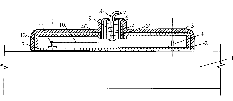
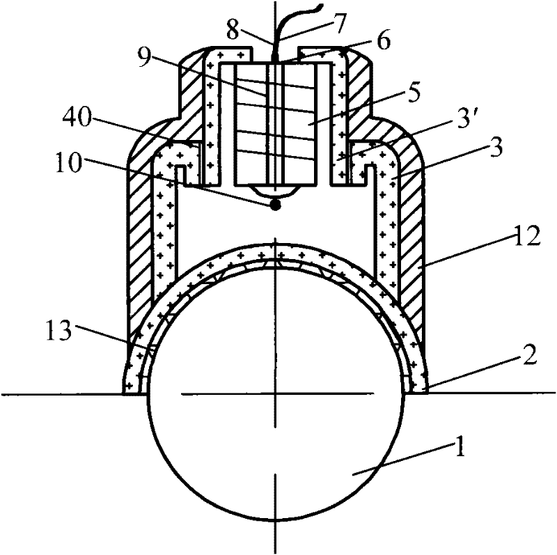
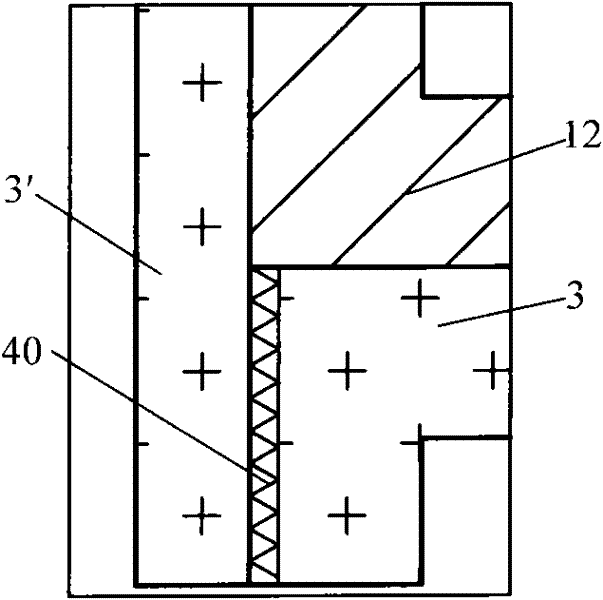
[0029] Such as figure 1 , figure 2 As shown, the present invention is a surface-attached type vibrating wire strain gauge, which comprises an upper chamber 3', a lower chamber 3, a signal pick-up device and a signal transmission system;

[0030] Wherein, the signal pick-up device is made of metal patch 2, vibrating wire support 4, vibrating wire 10 and vibrating wire clamping device 11; fixed on the central axis position of the upper surface of the metal patch 2 along the length direction, the metal patch 2 is affixed to the bottom of the lower chamber 3; the lower surface of the metal patch 2 is pasted with the steel bar 1 by an adhesive 13;

[0031] The signal transmission system includes a coil 5, a wire connector 6, a current wire 7 and a coil core 9; the coil 5 and the coil core 9 are fixed on the upper chamber 3', and the wire connector 6 is installed on the top of the co...


PUM


Abstract

The invention provides a surface pasting type vibration wire type reinforcing steel strain gauge, belonging to the field of civil engineering testing instruments. The invention is mainly composed of a chamber at the upper part, a chamber at the lower part, a signal picking device and a signal transmission system, wherein the chamber at the upper part and the chamber at the lower part are connected together through thread. The strain gauge is pasted on the reinforcing steel; when the reinforcing steel is deformed, the metallic paster feels the acting force and generates axial deformation to drive the two brackets to pull open to the two sides; the vibration wire is tightened, the fixed frequency of the vibration wire changes; and the stress vibration can be measured indirectly according tofrequency variation. The invention avoids the defect that reinforcing steel needs to be cut off in the traditional reinforcing steel vibration wire; when in use, the chamber at the lower part of the corresponding specification can be selected according to the specification of the reinforcing steel and is combined with the chamber at the upper part; the rubber sleeve around the strain gauge can avoid or reduce the influence of structure deformation of peripheral mortar or concrete and the like on the stress state of the strain gauge and reduce measurement error; the invention has the advantages of convenient processing, simple structure and low cost, and can be widely applicable to departments of machinery, earthquakes, mining industry and the like.

Description

technical field [0001] The invention belongs to the field of civil engineering testing instruments, relates to the fields of vibrating wire strain gauges and axial force gauges, in particular to a surface-attached vibrating wire type steel bar strain gauge for measuring the stress and strain of steel bars and anchor rods. Background technique [0002] At present, it is a widely used method to measure the strain of steel bar by using the vibrating wire steel bar strain gauge designed by the principle of resonance. During the use of this method, a lot of improvements have been made for different conditions of use, which greatly improves the measurement accuracy and practicability. This type of strain gauge is simple in design and can meet certain engineering measurement needs. But there are following shortcomings: [0003] (1) The shape of the traditional steel bar strain gauge (stress gauge) is cylindrical. When using it, the anchor rod and steel bar need to be cut off, wel...

Claims


Application Information

Patent Timeline
Patent Type & Authority Patents(China)
IPC IPC(8): G01B5/30G01L1/10
Inventor 吴顺川高永涛
Owner UNIV OF SCI & TECH BEIJING
Why Eureka
Try Eureka