
Polarization direction continuous collaborative regulating device for micro-Raman spectroscopy

A polarization direction and micro-Raman technology, applied in Raman scattering, installation, optics and other directions, can solve problems that affect accuracy and life, cannot provide devices, and experiments cannot be implemented

Inactive Publication Date: 2010-07-14
TIANJIN UNIV
View PDF0 Cites 7 Cited by
  • Summary
  • Abstract
  • Description
  • Claims
  • Application Information

AI Technical Summary

Problems solved by technology

However, none of the current microscopic Raman spectrometers can provide a device capable of realizing this function, and polarization adjustment is generally achieved by using independent devices for incident and scattering
In this way, on the one hand, it is impossible to realize the continuous adjustment of the polarization directions of incident light and astigmatism. On the other hand, the coordinated adjustment operation is quite cumbersome, often requiring the operator to walk repeatedly or cooperate with multiple experimenters.
Moreover, multiple adjustments are easy to bring dust or other debris into the spectrometer, which affects its accuracy and life.
Therefore, the existing experimental system that uses separate control of incoming and outgoing polarization is difficult to meet the experimental analysis that needs to adjust the polarization direction of incident light and scattered light at any time, and even makes some experiments impossible to implement.

Method used


Image

  • Polarization direction continuous collaborative regulating device for micro-Raman spectroscopy
  • Polarization direction continuous collaborative regulating device for micro-Raman spectroscopy
  • Polarization direction continuous collaborative regulating device for micro-Raman spectroscopy

Examples


Embodiment Construction

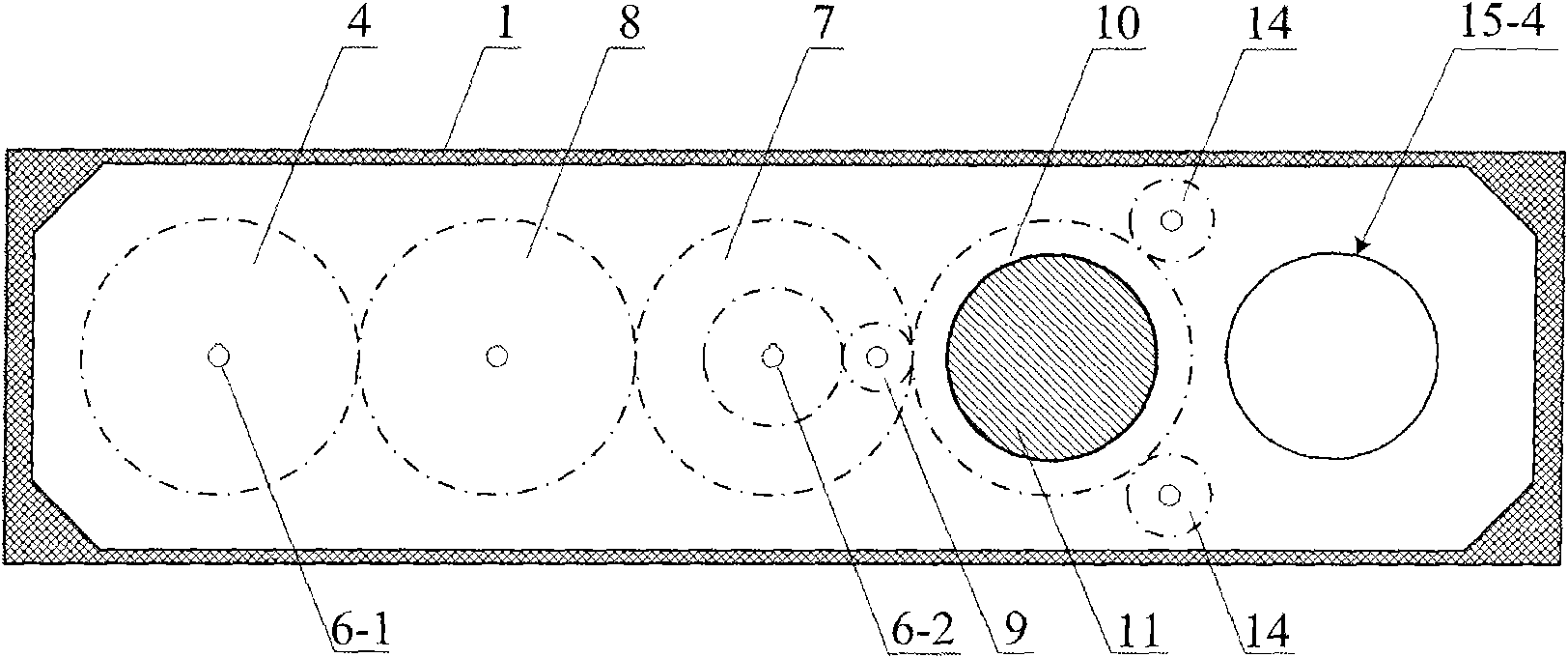
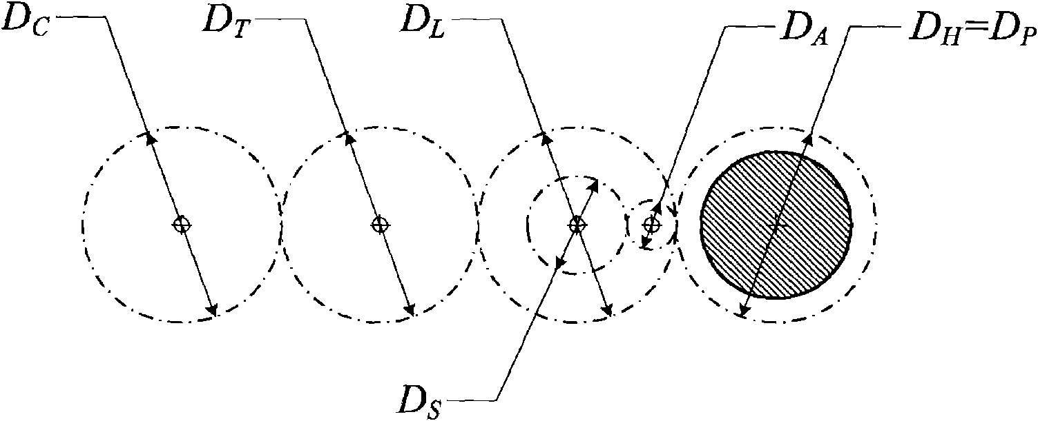
[0011] The following examples further illustrate the structural principle of the present invention. Attach Figure 1~2 The structure shown is to assemble the components, and the composition structure is: a rectangular box-shaped structure composed of a frame 1, an upper cover plate 2 and a lower cover plate 3. The driving gear 4 and the manual turntable 5 are coaxially keyed and fixed to the rotating shaft 6-1. The upper layer of the double gear 7 is a small wheel and the lower layer is a large wheel. The upper and lower gears are coaxially keyed to the rotating shaft 6-2. The index circle diameter of the large wheel is twice the diameter of the index circle of the small wheel. The transmission gear 8 meshes with the large gears of the driving gear 4 and the double gear 7 respectively. The half-wave plate gear 10 is a hollow gear ring, the hollow part of which is inserted into the half-wave plate 11. The polarizer gear 12 is also a hollow gear ring, the hollow circle part of w...


PUM


Abstract

The invention discloses a device for continuously and collaboratively regulating the incident light and scattered light polarization direction for a micro-Raman spectroscopy. A transmission gear is respectively meshed with a driving gear and the large gear of a double-link gear. A half-wave plate and a polaroid gear are hollow gear rings, and the hollow circles thereof are respectively inlaid into a half-wave plate and a polaroid. The half-wave plate gear and the polaroid gear share the same center of circle. A transition gear is arranged between the small gear of the double-link gear and the half-wave plate gear, the polaroid gear is meshed with the large gear of the double-link gear, and two positioning gears are meshed with the half-wave plate gear and the polaroid gear. Being a box-like structure, the device is implanted into the public optical path of incident light and scattered light of the Raman spectroscopy, a manual turntable serves as a control part, variable speed transmission is implemented through the transmission and the rotation of the gear structure and the double-link gear, the polarizer angle of the half-wave plate and the polarization angle of the Polaroid are collaboratively controlled through one-step operation, so as to conveniently realize the continuous collaborative regulation of the incident light and scattered light polarization direction with high precision.

Description

Technical field [0001] The invention belongs to optical machinery, and specifically relates to a device for continuous and coordinated adjustment of the polarization directions of incident light and scattered light for a micro-Raman spectrometer. Background technique [0002] As we all know, the Raman microscope is an advanced experimental analysis instrument that combines modern optical microscopy technology and Raman scattering spectrometer, and is widely used in experimental analysis in many fields. Using the good polarization of the laser to analyze the Raman scattering characteristics of the studied object under various polarized light excitations is an important application method of Raman microscopy. Many of the measurement tasks require the incident light and scattering at any time in the experiment. The polarization direction of the light is continuously coordinated. Among them, continuous means that the polarization angle can be adjusted to any angle within the circle,...

Claims


Application Information

Patent Timeline
IPC IPC(8): G02B7/00G01N21/65
Inventor 仇巍亢一澜李秋雷振坤
Owner TIANJIN UNIV
Learn More