
Backflush device for a filter system

A filter system and filter body technology, which is applied in the direction of filtration separation, fixed filter element filter, transportation and packaging, etc., can solve the problems of increasing the flow resistance of the filter body, and achieve the effect of performance improvement and uniform backwashing effect

Active Publication Date: 2010-07-14
FILTRATION GRP GMBH
View PDF0 Cites 2 Cited by
  • Summary
  • Abstract
  • Description
  • Claims
  • Application Information

AI Technical Summary

Problems solved by technology

This increases the flow resistance of the filter body

Method used


Image

  • Backflush device for a filter system
  • Backflush device for a filter system
  • Backflush device for a filter system

Examples


Embodiment Construction

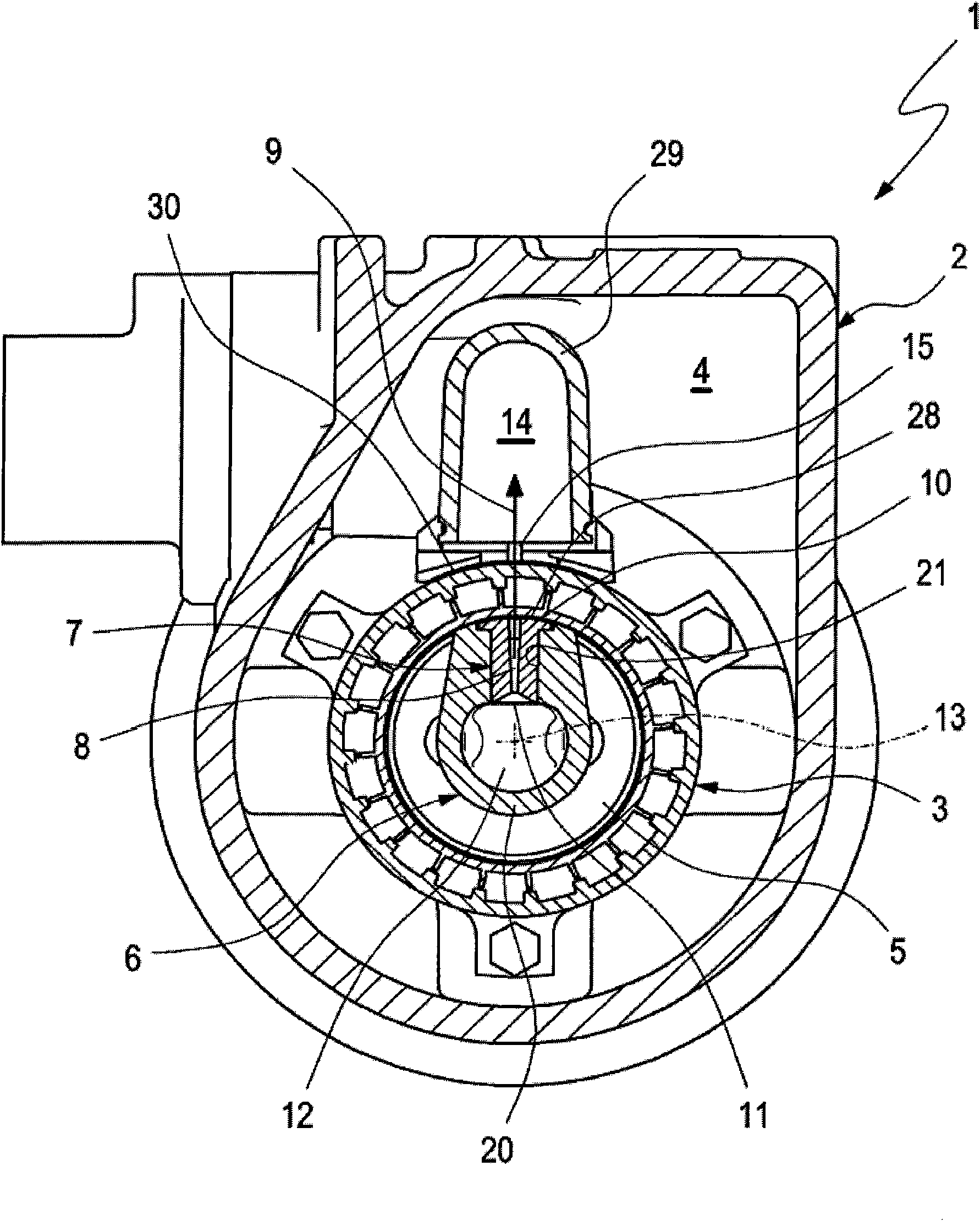
[0018] according to figure 1 , the filter system 1 has a housing 2 in which a filter body 3 is accommodated. In the housing 2 , the filter body 3 separates the inlet space 4 or the inlet side 4 from the clean space 5 or the clean side 5 . The filter body 3 has a cylindrical configuration and is preferably constructed in such a way that it is flowed through radially from the outside to the inside during filtration operation. As a result, the inlet space 4 is located radially outside the filter body 3 , whereas the clean space 5 is surrounded by the filter body 3 . The filter body 3 can be, for example, a known edge split filter. Basically, any other desired design for the filter body 3 is also conceivable, such as a filter body composed of micro-mesh material or pleated material. The filter system 1 is used to remove impurities from the liquid. In particular, solid particles can be filtered from the liquid. In principle, it can also filter out solid or liquid particles fro...


PUM


Abstract

The invention relates to a backflush device (6) for a filter system (1) for removing impurities from a fluid, the backflush device (6) serving to backflush a filter body (3) in the filter system separating the clean side (5) from the inlet side (4), and comprising at least one backflush nozzle (7) for applying a rinse medium to the filter body (3), said nozzle comprising at least one opening (8) through which the rinse medium flows in a flow direction (9) during backflushing and exits the backflush nozzle (7). In order to improve the effectiveness of the backflushing, the at least one opening is designed as a slit opening (8) extending transverse to the flow direction (9) in a straight line having a constant cross-sectional profile (16) comprising a nozzle segment (17) expanding the flow direction (9).

Description

technical field [0001] The invention relates to a backflushing device for a filter system for removing impurities from a liquid, the backflushing device being used in a filter system for backflushing a filter body in a filter system, the filter body connecting the clean side with the The inlet side is separated. Background technique [0002] Filtration systems in industrial or stationary applications are used in a variety of processes, for example, to filter liquid or solid particles from gas streams, or to remove solid particles from liquid streams. In this way, the respective filter system uses at least one filter body which separates the inlet space from the clean space within the system. The filter body then has a filter material through which the respective liquids are flowed through which are filtered out since the filter material is impermeable to particles. During the cleaning operation or the filtering operation, the filtered particles may accumulate or deposit on...

Claims


Application Information

Patent Timeline
IPC IPC(8): B01D29/15
CPCB01D46/0069B01D29/15B01D29/682B01D46/715
Inventor 马库斯·普拉赫尔阿尔贝特·希克迪特里希·施特策
Owner FILTRATION GRP GMBH
Learn More