

Air blowout structure and air blowout unit for air-floating conveyor apparatus, and air-floating conveyor apparatus having the same
A conveying device and air suspension technology, applied in the direction of conveyor objects, conveyors, transportation and packaging, etc., can solve the problems of difficult maintenance operations of the upper wall part 103, decreased positioning accuracy of the substrate, and inability to increase the acceleration and deceleration speed, etc., to achieve maintenance Ease of operation, increased acceleration and deceleration, and shortened conveying time
- Summary
- Abstract
- Description
- Claims
- Application Information
AI Technical Summary
Problems solved by technology
Method used
Image

Examples
Embodiment Construction
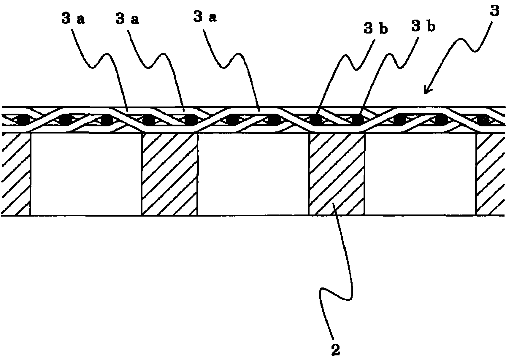
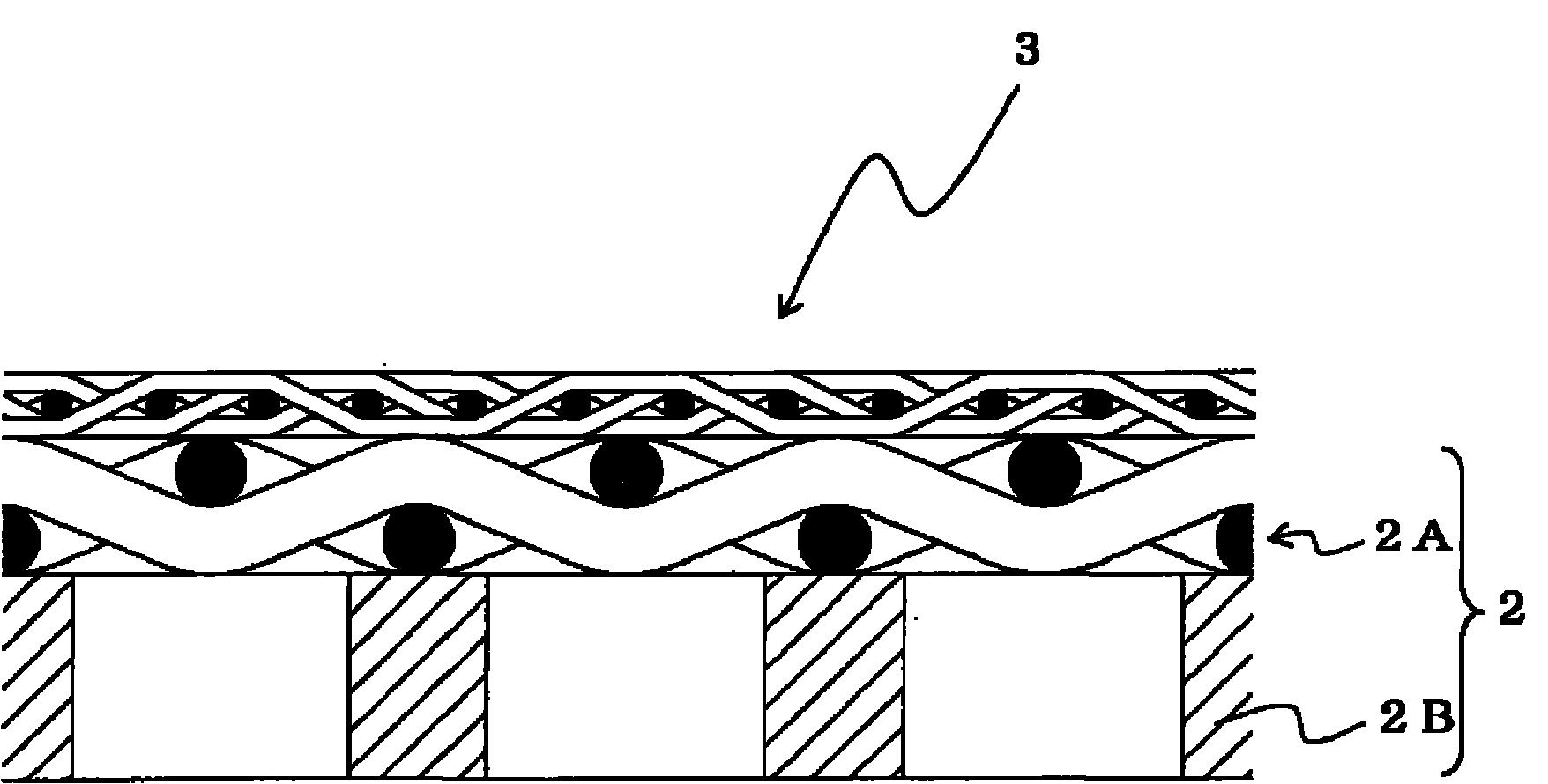
[0038] The air blowing structure of the air levitation conveying device of the present invention can be applied to an air levitating conveying device that suspends a sheet with air and conveys it with conveying rollers. The reinforcing member having a porosity arranged at the lower part of the woven wire mesh is constituted.
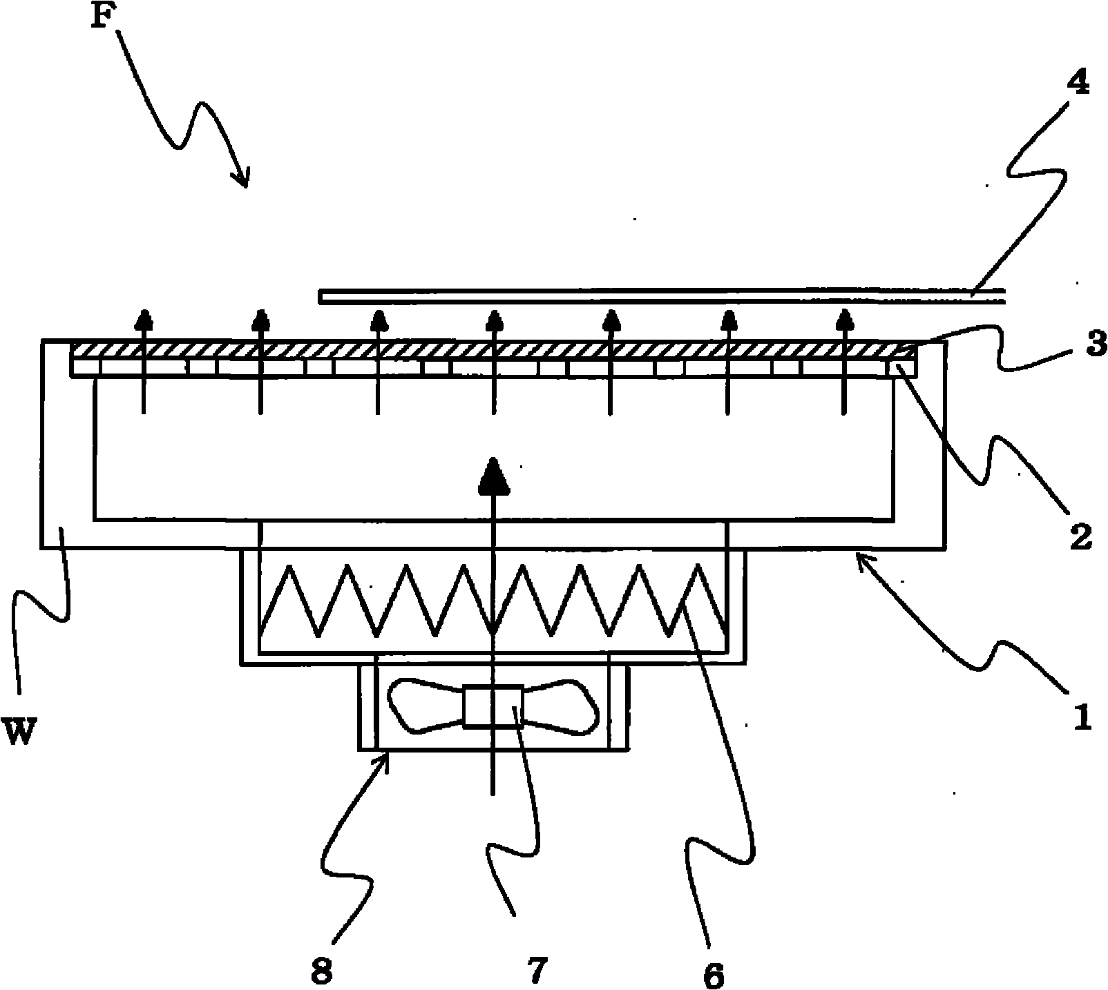
[0039] Here, the meaning of the terms used in the present invention will be described. In the present invention, the so-called air levitation conveying device includes a device that has a unit that levitates and supports a large and very thin glass substrate used in a flat panel display such as a liquid crystal display panel or a plasma display panel in a non-contact manner, or has the above-mentioned unit and conveying device using conveying rollers.
[0040] The air blowing structure refers to a porous structure capable of supplying air under pressure in the chamber of the air blowing unit to the upper surface portion of the unit (the lower surface si...
PUM
 Abstract
Description
Claims
Application Information