Wind driven electric power generator

A technology for a wind power generation device and a bearing part, which is applied to wind turbine components, wind energy power generation, wind turbines, etc., can solve problems such as damage to rolling elements

Inactive Publication Date: 2010-07-14
MITSUBISHI HEAVY IND LTD
View PDF1 Cites 8 Cited by
  • Summary
  • Abstract
  • Description
  • Claims
  • Application Information

AI Technical Summary

Problems solved by technology

[0006] However, since the above-mentioned oil supply pump cannot be started during a power failure, there are problems in the main bearing part such as damage to rolling elements caused by oil cut-off during idling.

Method used


Image

  • Wind driven electric power generator
  • Wind driven electric power generator
  • Wind driven electric power generator

Examples


Embodiment Construction

[0030] Below, refer to Figure 1 to Figure 4 One embodiment of the wind power generator of the present invention will be described.

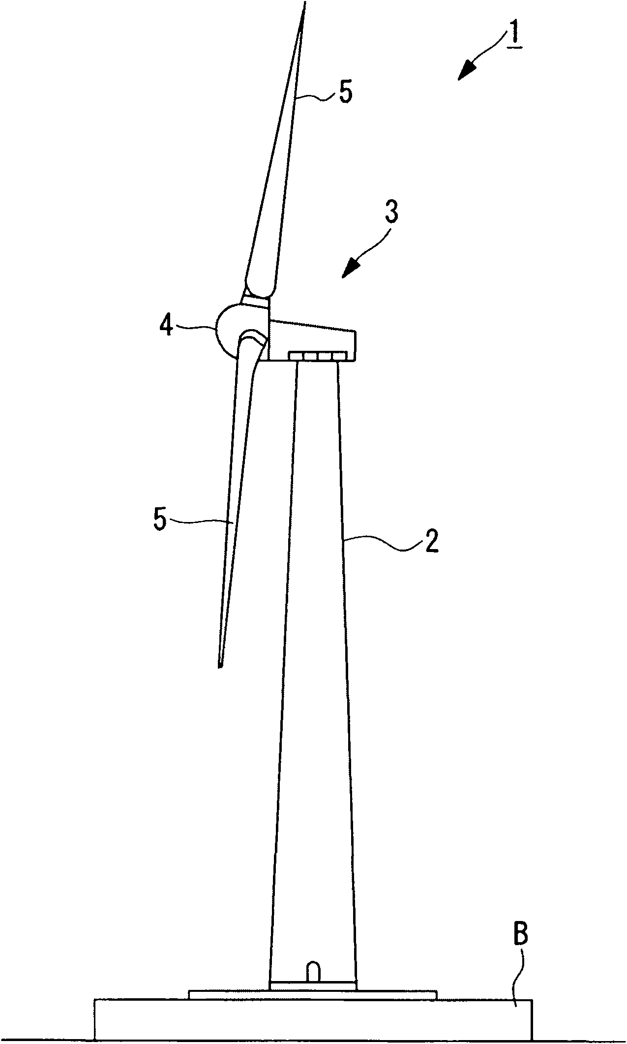
[0031] exist image 3 The wind power generation device 1 shown in has: a pillar (also referred to as a "tower") 2 erected on a foundation B, a nacelle 3 arranged on the upper end of the pillar 2, and supported in a rotatable manner around a substantially horizontal transverse rotation axis. And be located at the rotor head 4 of the nacelle 3.

[0032] Around the rotation axis of the rotor head 4, a plurality of (for example, three) windmill rotor blades 5 are mounted radially. As a result, the force of the wind blowing toward the wind turbine rotor blades 5 from the direction of the rotation axis of the rotor head 4 is converted into power for rotating the rotor head 4 around the rotation axis.

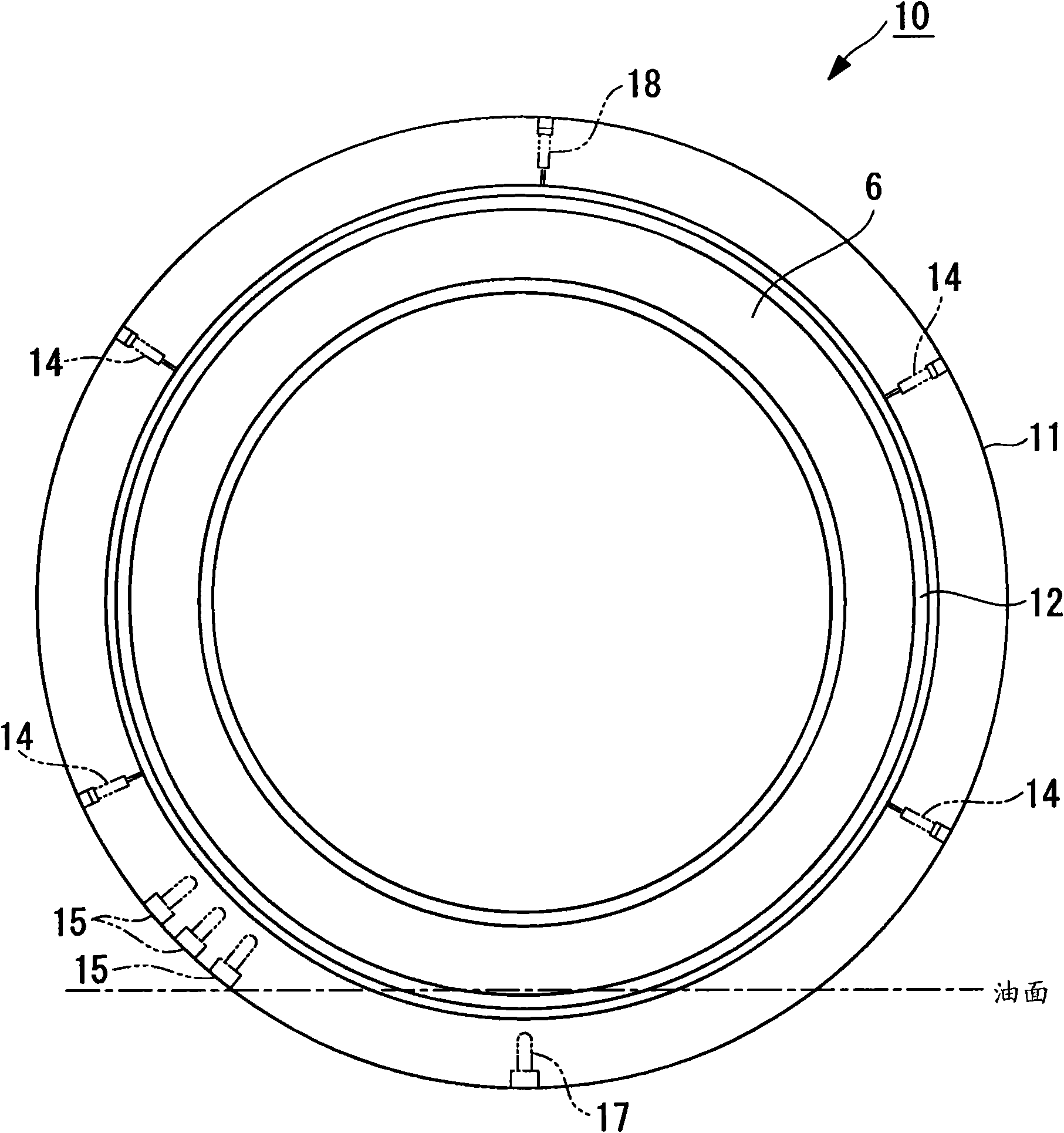
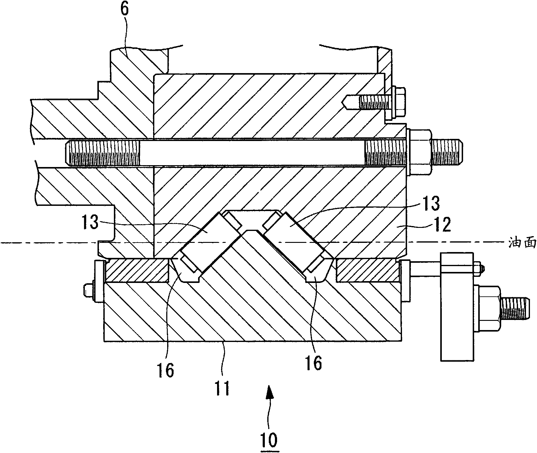
[0033] The above-mentioned wind power generator 1 has a main bearing portion 10 that supports a main shaft 6 arranged substantially horizontally. T...


PUM


Abstract

A wind driven electric power generator in which, even if an impeller runs idle during an electric power failure, damage to rolling bodies due to run out of lubricant at a main bearing section (10) is reliably prevented. In the wind driven electric power generator, the main bearing section (10) for a main shaft (6) placed in the lateral direction has an oil feed opening (14) and a drain opening (15) for lubricant. The lubricant supplied from an oil supply pump flows into the main bearing section (10) from the oil feed opening (14) and flows out of the drain opening (15) for circulation. The drain opening (15) is provided above the center of lower rolling bodies arranged in the main bearing portion (10).

Description

technical field [0001] The present invention relates to a wind power generator, in which a main shaft rotated by wind force drives a generator to generate electricity. Background technique [0002] A wind power generator is a device in which a rotor head having windmill blades is rotated by wind force, and the rotation is increased by a speed increaser to drive a generator to generate electricity. Therefore, in the wind power generator, there are sliding parts that require lubrication, such as main bearings, for example. [0003] As a prior art related to lubrication, there is known a lubricating structure of a mechanical lubricator that supplies a sufficient amount of oil to a mechanical seal and maintains good sealing performance of the mechanical seal. In this prior art, in order to release pressure in a space formed between a bearing that rotatably supports the rotating shaft and a mechanical seal fitted on the outer periphery of the rotating shaft, an air release hole ...

Claims


Application Information

Patent Timeline
Patent Type & Authority Applications(China)
IPC IPC(8): F03D11/00
CPCF16C33/6685F16C19/38Y02E10/72F03D11/0008F16C2300/14Y02E10/721Y02E10/722F03D80/70F16C19/52F16C33/664F16C33/6659F16C2360/31F05B2240/50
Inventor 冈野靖高柳和史野田善友
Owner MITSUBISHI HEAVY IND LTD
Why Eureka
Try Eureka