Printer

A technology for printing machines and cranes, which is applied in the direction of printing machines, printing, rotary printing machines, etc., can solve problems such as machine damage, temperature treatment liquid ingress, and lubricating ability reduction, so as to achieve the effect of reducing work

Inactive Publication Date: 2010-07-21
HEIDELBERGER DRUCKMASCHINEN AG
View PDF10 Cites 9 Cited by
  • Summary
  • Abstract
  • Description
  • Claims
  • Application Information

AI Technical Summary

Problems solved by technology

There is a risk that, in the event of a leak caused by a fault, temperature-processing liquid (water) enters the lubricant circuit and the oil is contaminated
Due to this contamination, the lubricating ability of said oil will be reduced, which will lead to machine damage

Method used


Image

  • Printer
  • Printer
  • Printer

Examples


Embodiment Construction

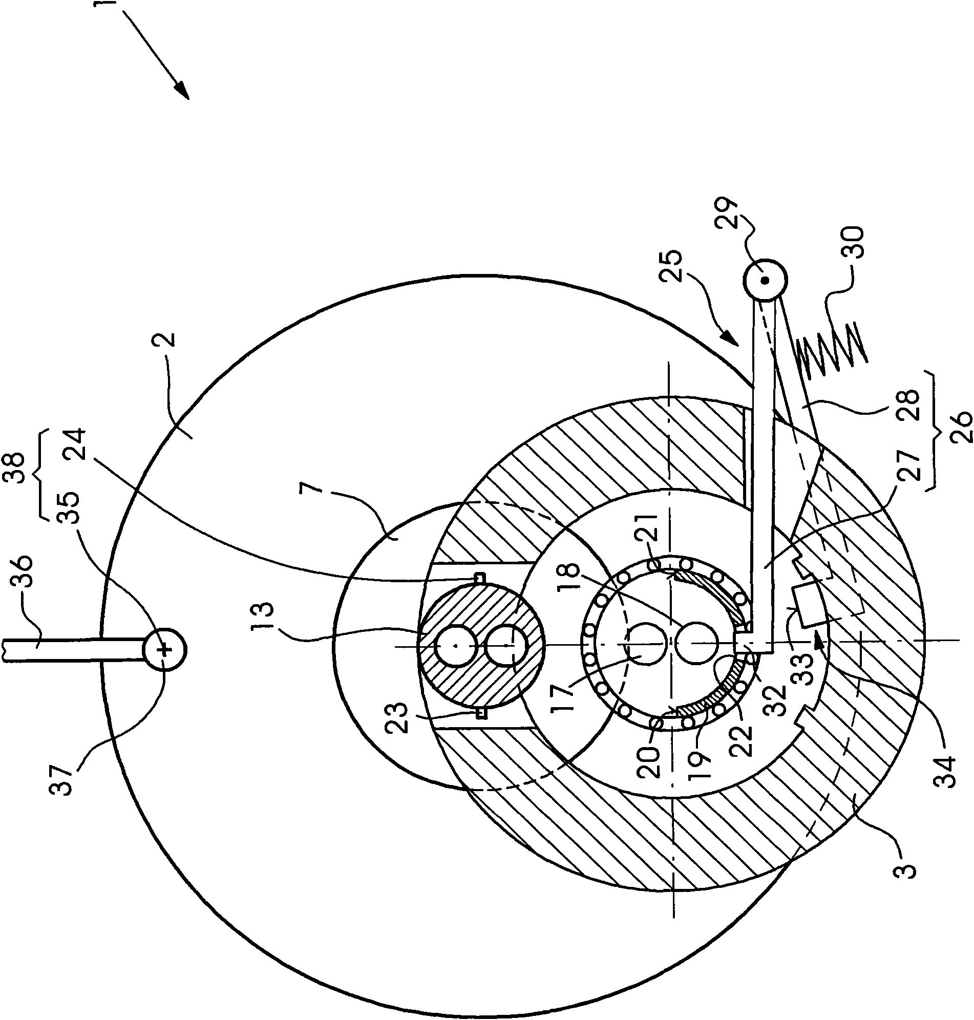
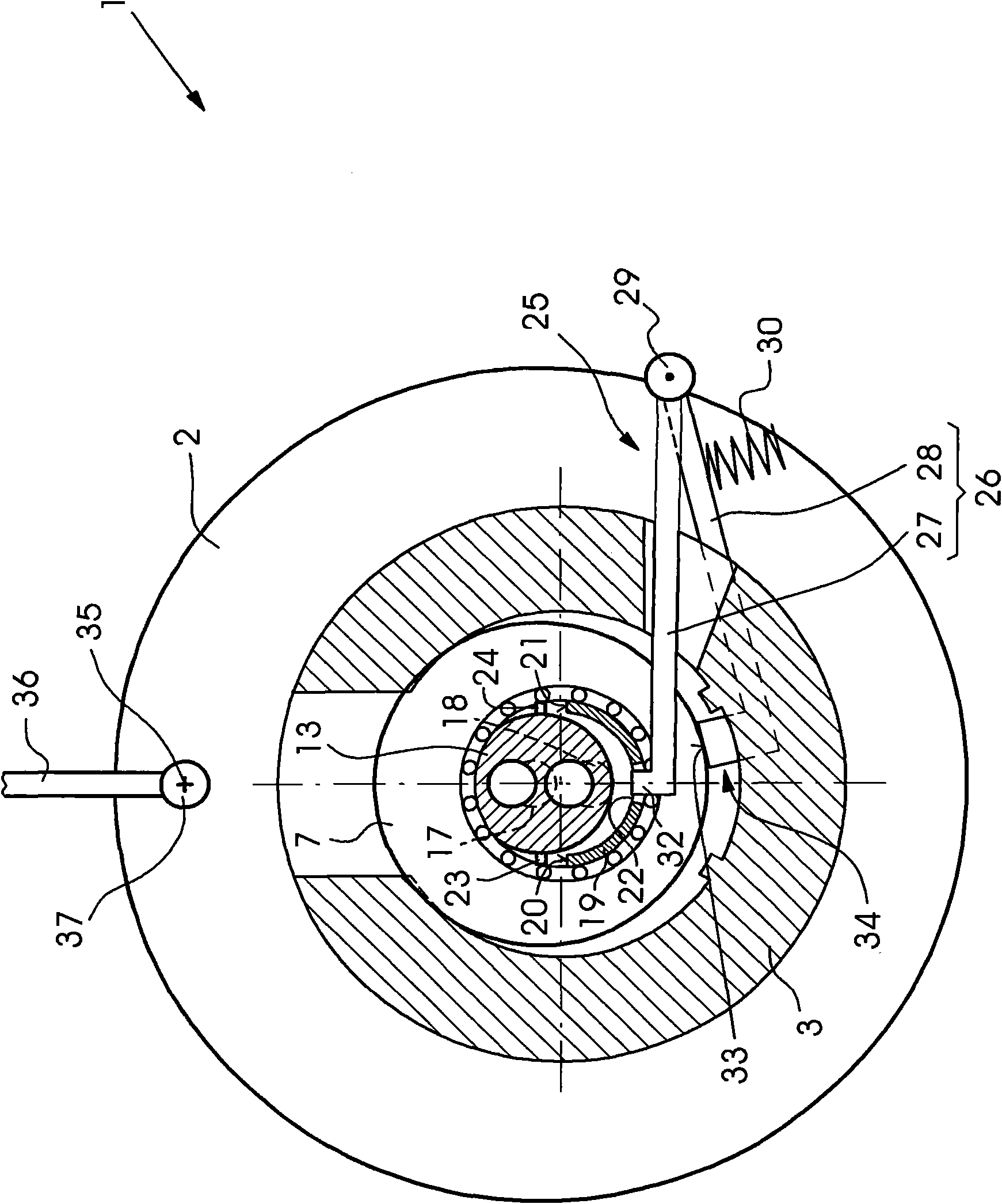
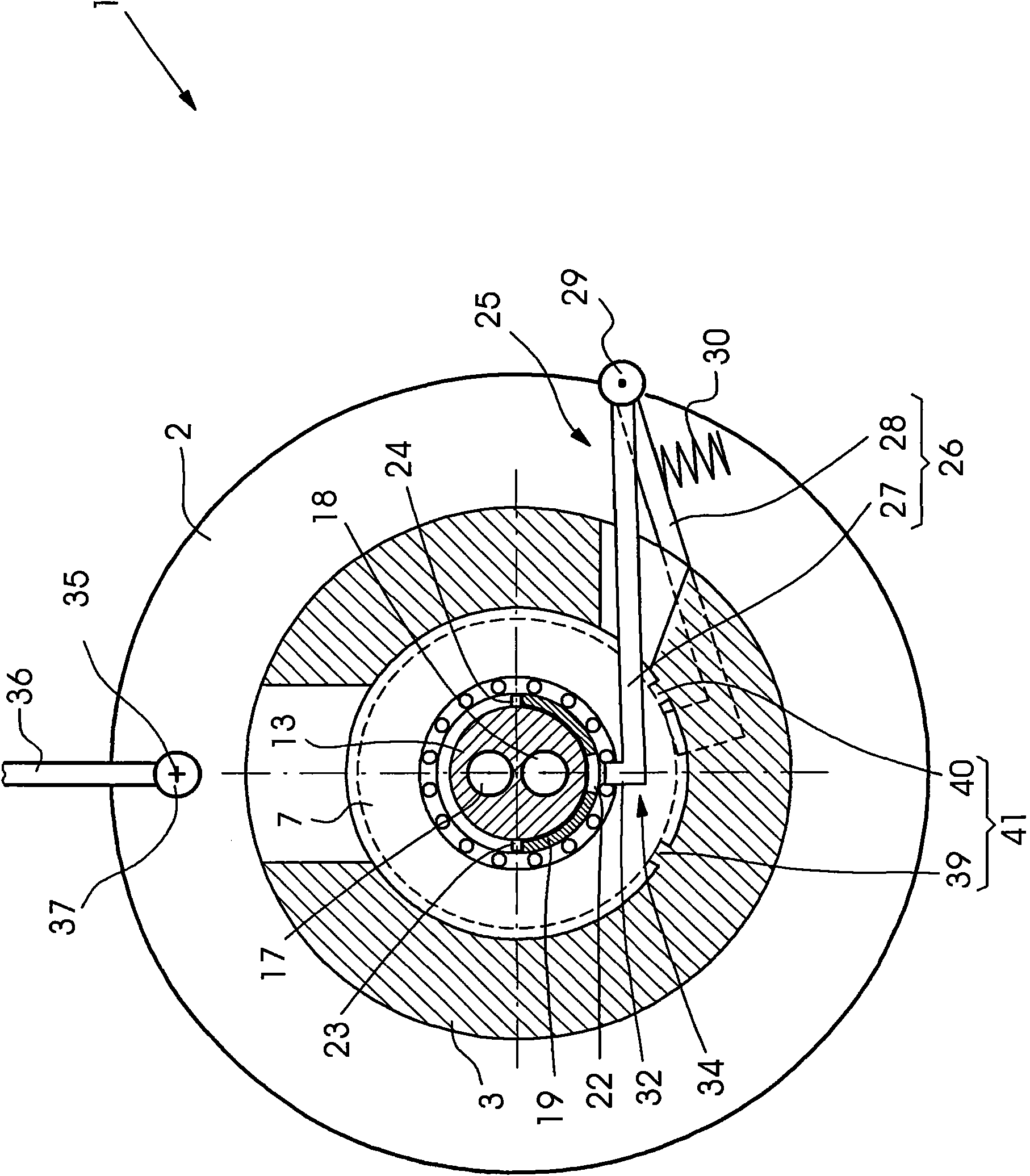
[0019] in Figure 1 to 4 It is shown that the printing press 1 includes a roller 2 and roller locks 3, 4 arranged to receive the roller. The printing press 1 is an offset printing press and the roller 2 is an anilox roller of an anilox inking device. One roller lock 3 is on the operating side BS of the printing press 1 and the other roller lock 4 is on the drive side AS.

[0020] The roller 2 has journals 5, 6, on which rolling bearings 7, 8 sit. On the drive side AS, a drive shaft 9 is rotatably supported in the wall of the frame and in the roller lock 4 via rolling bearings. A gear 10 is connected to the drive shaft 9 without relative rotation. The gear is a component of a gear transmission.

[0021] The first clutch half of a drive clutch 11 is located on the journal 6, and the second clutch half of the drive clutch 11 is located on the end of the drive shaft 9 opposite to the gear 10. The drive clutch 11 is used to transmit torque from the drive shaft 9 to the roller 2 and i...


PUM


Abstract

The invention relates to a printer, which includes: a roller wherein a temperature processing liquid flows through, roller locks used for the roller and configured to a rapidly replaced device, and a pipeline clutch, using the pipeline of the temperature processing liquid to connect to the roller, wherein, the pipeline clutch has a first clutch half part on the roller and a second clutch half part on the pipeline. Also provided is a positioning device for automatically performing modulation or positioning of at least one of the clutch half parts relative to the other when the roller is inserted in the roller locks.

Description

Technical field [0001] The present invention relates to a printing machine, which includes: a roller through which a temperature treatment liquid flows, a roller lock configured as a quick change device for the roller, and a pipeline for the temperature treatment liquid and the A pipeline clutch connected to the rollers, wherein the pipeline clutch has a first clutch half on the roller and a second clutch half on the pipeline. Background technique [0002] One such printing press is described in DE 102005049176 A1. Here, the roller is supported in a roller lock configured as a quick change device or a quick lock device, so that the roller can be quickly removed from the roller lock and the printing press by the operator of the printing press and placed in the roller lock and In the printing press. Considering the maintenance of the rollers performed outside the printing press, the structure of the roller lock as a quick change device and the removal and reinsertion of the rolle...

Claims


Application Information

Patent Timeline
Patent Type & Authority Applications(China)
IPC IPC(8): B41F31/00B41F31/30
CPCB41F13/20B41F13/22
Inventor C·卡岑贝格尔R·米勒D·沙夫拉特B·施瓦布
Owner HEIDELBERGER DRUCKMASCHINEN AG
Why Eureka
Try Eureka