Cooling device

A technology of cooling device and cooling chamber, which is applied in the direction of packaging, etc., can solve the problems of normal transportation of materials that affect normal operation, incomplete blanking, etc., and achieve the effects of reasonable cooling and transportation, saving time and improving work efficiency

Inactive Publication Date: 2010-07-21
TIBET QIZHENG TIBETAN MEDICINE
View PDF11 Cites 10 Cited by
  • Summary
  • Abstract
  • Description
  • Claims
  • Application Information

AI Technical Summary

Problems solved by technology

[0007] For this reason, the technical problem to be solved by the present invention is the cooling device in the prior art. The screw agitating conveyor provided in it only transmits the material in one direction, which easily causes the material to accumulate at the end of the screw agitating conveyor along the conveying direction. , which affects the normal operation of the drive shaft of the screw agitating conveyor and the normal conveying of materials, and also makes the blanking of the material in the process of conveying incomplete, thereby providing a method that can prevent the material from being trapped at the end of the screw agitating conveyor while ensuring the normal conveying of the material. Cooling device where internal accumulation affects conveying efficiency

Method used


Image

  • Cooling device
  • Cooling device
  • Cooling device

Examples


Embodiment Construction

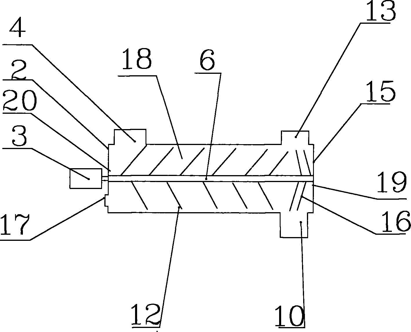
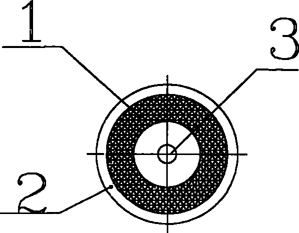
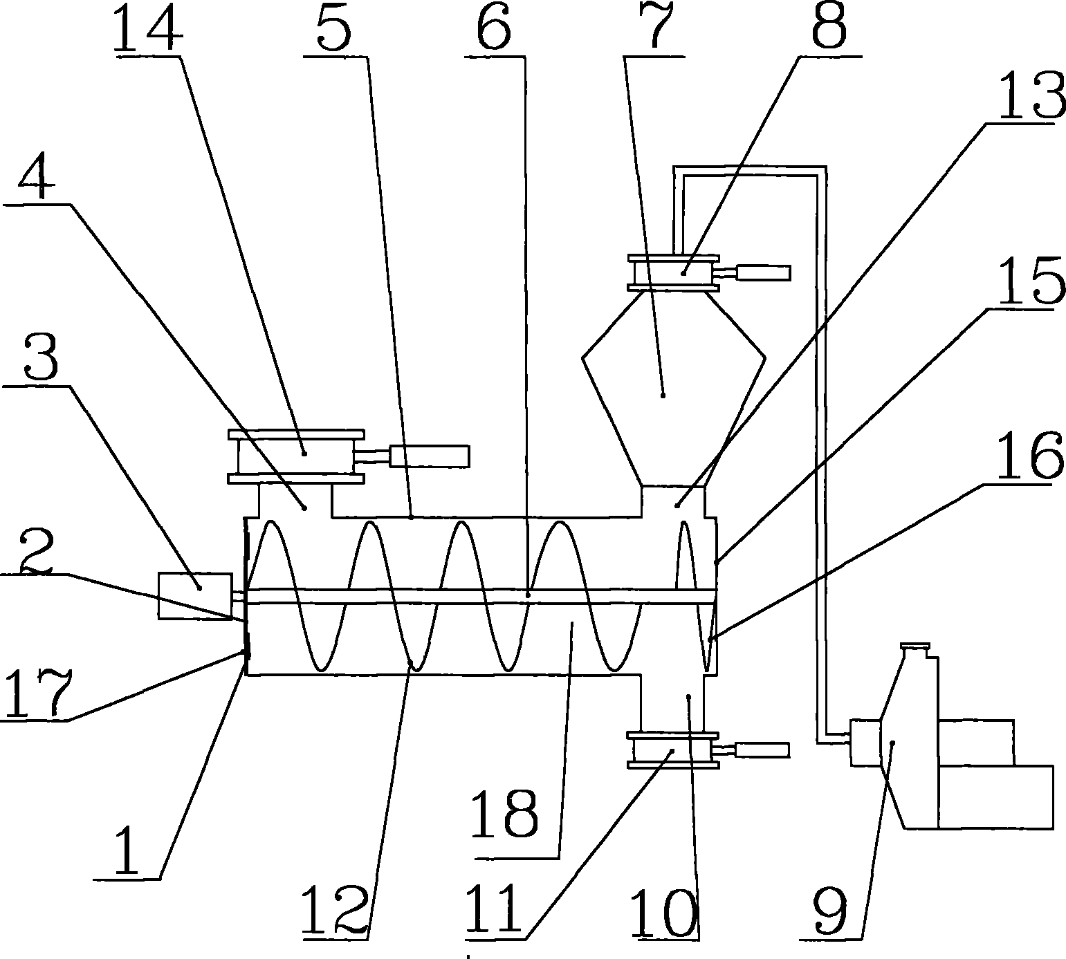
[0034] Cooling device of the present invention such as figure 1 As shown, it can be seen from this figure that it includes a cylindrical cooling bin 5, and the cooling bin 5 is laterally provided with a front end cover 2 and a rear end cover 15; The front end cover 2 is provided with a cooling bin material inlet 4, and a cooling bin material outlet 10 is provided at the bottom of the cooling bin 5 and near the rear end cover 15; in addition, on the front end cover 2 of the cooling bin 5 A cooling air inlet 17 is provided, and a cooling air outlet 13 is arranged on the top of the cooling chamber 5 and near the rear end cover 15, so that the cooling air enters the cooling chamber 5 through the cooling air inlet 17 and passes through After circulating, it is discharged from the cooling air outlet 17. In order to realize the conveying of the material while cooling the material, the cooling device of the present invention is also provided with a screw agitating conveyor 18 in the ...


PUM


Abstract

A cooling device comprises a cooling bin. The cooling bin is provided with a front end cover, a rear end cover, a material inlet, a material outlet, a cooling air inlet, a cooling air outlet and a helical mixing conveyor, wherein the helical mixing conveyor comprises a transmission shaft connecting the front end cover and the rear end cover; the transmission shaft is provided with positive helical slices and reverse helical slices; and the transfer directions of the positive helical slices and the reverse helical slices are opposite. The cooling device solves the problem that the materials are piled at the ends because the helical mixing conveyors arranged in the cooling devices in the prior art transfer the materials only towards one direction, and the problem of indirect cooling effect of the cooling air in the prior art, and can avoid the transfer efficiency from being affected because the materials are piled at the ends of the helical mixing conveyors and improve the cooling effect of the cooling air while ensuring normal transfer of the materials.

Description

technical field [0001] The invention relates to a cooling device, in particular to a cooling device for powder materials. Background technique [0002] Cooling device is a kind of equipment with cooling effect, which is widely used in production, processing and other industries. The cooling device in the prior art is generally provided with an air inlet and an air outlet, and a stirring and conveying device is provided inside it for stirring and conveying the material to be cooled. The commonly used stirring and conveying device is a screw conveying device. [0003] In the utility model patent application submitted by the applicant with the application number 201020000178.3, a steam sterilization device is disclosed. The steam sterilization device is provided with a cooling chamber, and the cooling chamber is a cavity with a cooling interlayer The cavity is provided with a cooling bin inlet and a cooling bin outlet, and a screw agitating conveyor is arranged inside the cavi...

Claims


Application Information

Patent Timeline
Patent Type & Authority Applications(China)
IPC IPC(8): B65G33/26B65G33/24B65G33/14
Inventor 马月鲤王守东冯治聪
Owner TIBET QIZHENG TIBETAN MEDICINE
Why Eureka
Try Eureka