Device for reducing driving voltage of blue phase liquid crystal display
A display driver and blue-phase liquid crystal technology, applied in the direction of instruments, nonlinear optics, optics, etc., can solve the problems that are difficult to realize and have very high material requirements, and achieve the effect of reducing the driving voltage, saving energy, and increasing the lateral effective electric field
- Summary
- Abstract
- Description
- Claims
- Application Information
AI Technical Summary
Problems solved by technology
Method used
Image
Examples
Embodiment 1
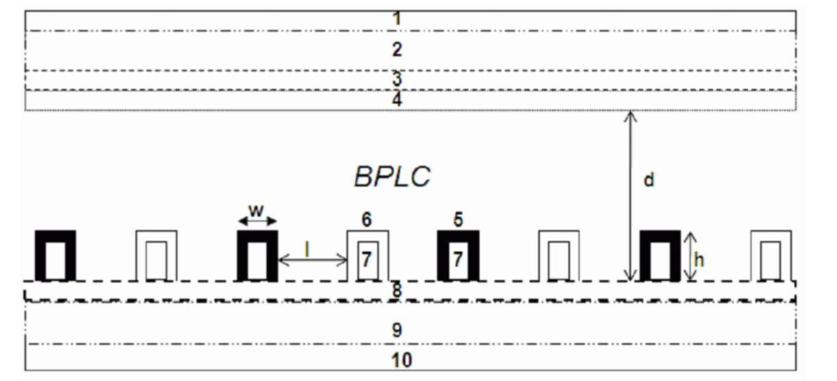
[0024] Such as figure 1 As shown, this embodiment includes: an upper polarizer 1, an upper substrate 2, a protective film 3, a color filter film 4, a blue phase liquid crystal (BPLC), N Pixel electrodes 5, N Common electrodes 6, and 2N protrusions 7 , insulating layer 8, lower substrate 9 and lower polarizer 10, wherein: the lower surface of upper polarizer 1 is connected with the upper surface of upper substrate 2, the lower surface of upper substrate 2 is connected with the upper surface of protective film 3, protective film 3 The lower surface of the protrusion 7 is connected to the upper surface of the color filter film 4, one surface of the protrusion 7 is connected to the upper surface of the insulating layer 8, and the rest of the protrusion 7 is located in the Pixel electrode 5 or the Common electrode 6, and the Pixel electrode 5 and the Common electrode 6 Arranged alternately at equal intervals, and the distance between the Pixel electrodes 5 and the Common electrodes...
Embodiment 2
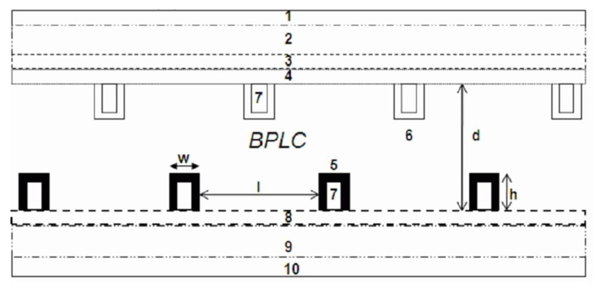
[0031] Such as image 3 As shown, this embodiment includes: an upper polarizer 1, an upper substrate 2, a protective film 3, a color filter film 4, a blue phase liquid crystal, N Pixel electrodes 5, N Common electrodes 6, 2N protrusions 7, an insulating layer 8. The lower substrate 9 and the lower polarizer 10, wherein: the lower surface of the upper polarizer 1 is connected to the upper surface of the upper substrate 2, the lower surface of the upper substrate 2 is connected to the upper surface of the protective film 3, and the lower surface of the protective film 3 Connected to the upper surface of the color filter film 4, one surface of the N protrusions 7 is connected to the lower surface of the color filter film 4, one surface of the N protrusions 7 is connected to the upper surface of the insulating layer 8, and connected to the color filter film 4 The remaining part of the protrusion 7 is located in the Common electrode 6, and the remaining part of the protrusion 7 con...
Embodiment 3
[0036] Such as Figure 5 As shown, the difference between this embodiment and Embodiment 1 is that the cross section of the protrusion 7 is trapezoidal, the base angle of the trapezoid is 75°, the long base is 3.8 μm, and the height is 3.9 μm.
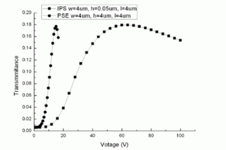
[0037] Such as Figure 6 As shown, in this embodiment, the driving voltage is lowered to 21V. Although the effect of lowering the voltage is not as good as that of Embodiment 1, the transmittance of light is relatively increased by 2%.
PUM
| Property | Measurement | Unit |
|---|---|---|
| thickness | aaaaa | aaaaa |
| thickness | aaaaa | aaaaa |
Abstract
Description
Claims
Application Information
 - R&D
- Intellectual Property
- Life Sciences
- Materials
- Tech Scout
- Unparalleled Data Quality
- Higher Quality Content
- 60% Fewer Hallucinations
Browse by: Latest US Patents, China's latest patents, Technical Efficacy Thesaurus, Application Domain, Technology Topic, Popular Technical Reports.
© 2025 PatSnap. All rights reserved.Legal|Privacy policy|Modern Slavery Act Transparency Statement|Sitemap|About US| Contact US: help@patsnap.com


