Multi-mode redundant field suppression protection loop
A multi-mode redundancy and protection circuit technology, applied in emergency protection circuit devices, electrical components, etc., can solve the problem of low reliability of demagnetization, and achieve the effect of prolonging service life and improving reliability.
- Summary
- Abstract
- Description
- Claims
- Application Information
AI Technical Summary
Problems solved by technology
Method used
Image
Examples
Embodiment 1
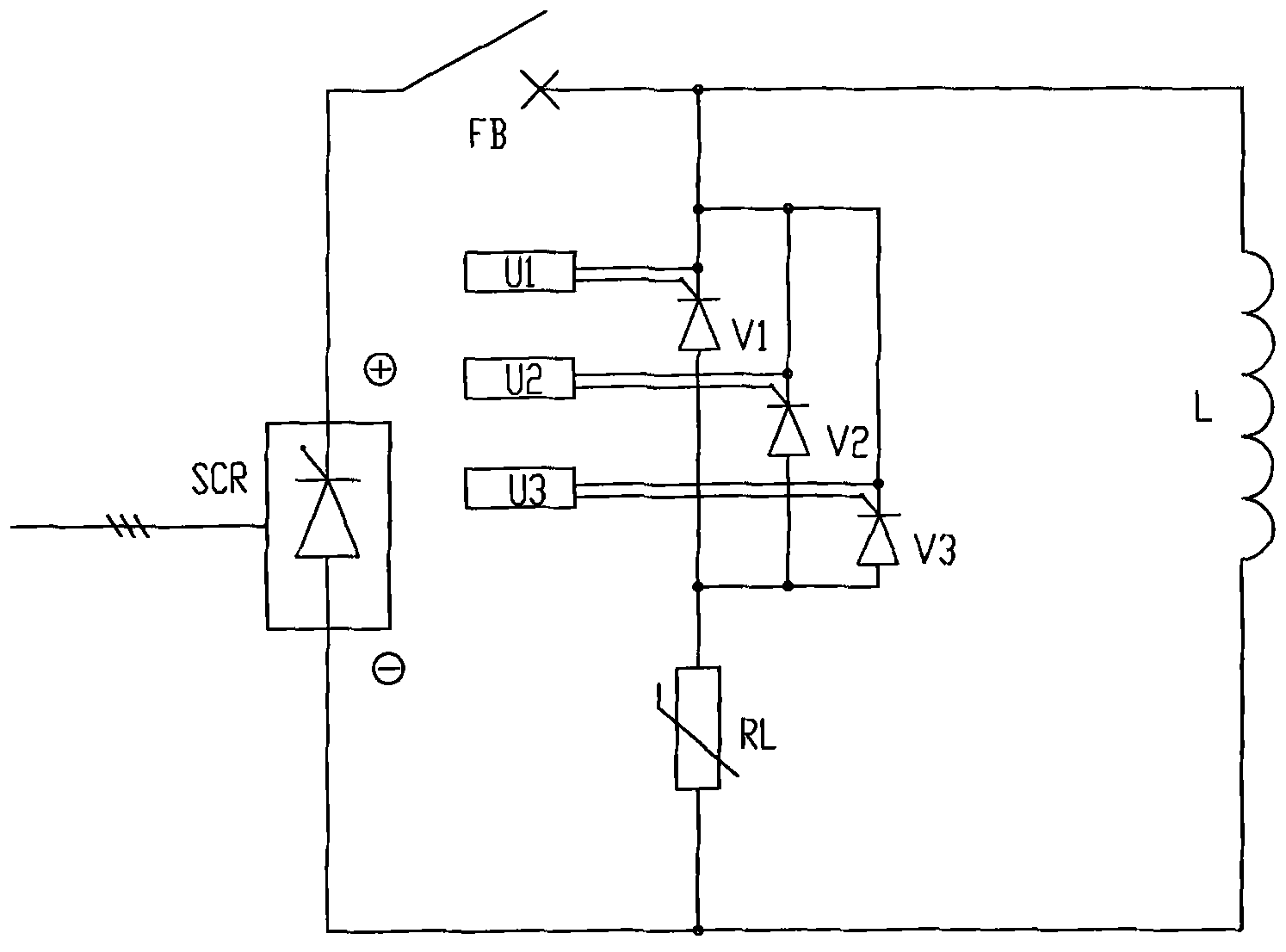
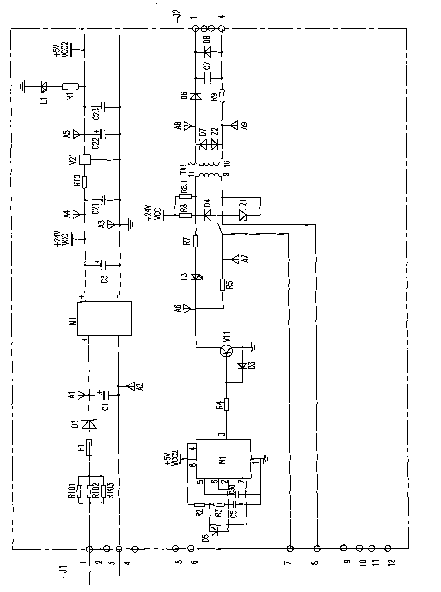
[0026]Multi-mode redundant de-excitation protection circuit, including thyristor jumper and its control trigger, the first thyristor jumper V1, the second thyristor jumper V2, the third thyristor jumper V3 is three independent thyristor jumpers with the same technical parameters. They are all high-power thyristors with high blocking voltage. The rated current is 3500A, and the forward and reverse blocking voltages are 5200V. The negative terminals of the first thyristor jumper V1, the second thyristor jumper V2, and the third thyristor jumper V3 are connected in parallel with each other and then connected to the positive pole of the generator field winding L, and the positive terminals are connected to each other After parallel connection, it is connected to one end of the SiC non-linear resistance, and the other end of the SiC non-linear resistance is connected to the negative pole of the generator field winding L. The first thyristor jumper V1, the second thyristor jumper V2,...
Embodiment 2
[0029] Multi-mode redundant de-excitation protection circuit, including thyristor jumper and its control trigger, the first thyristor jumper V1, the second thyristor jumper V2, the third thyristor jumper V3 is three independent thyristor jumpers with the same technical parameters. They are all high-power thyristors with high blocking voltage. The rated current is 3500A, and the forward and reverse blocking voltages are 5200V. The negative terminals of the first thyristor jumper V1, the second thyristor jumper V2, and the third thyristor jumper V3 are connected in parallel with each other and then connected to the positive pole of the generator field winding L, and the positive terminals are connected to each other After parallel connection, it is connected to one end of the linear resistor, and the other end of the linear resistor is connected to the negative pole of the generator field winding L. The first thyristor jumper V1, the second thyristor jumper V2, and the third thyr...
Embodiment 3
[0032] Multi-mode redundant de-excitation protection circuit, including thyristor jumper and its control trigger, the first thyristor jumper V1, the second thyristor jumper V2, the third thyristor jumper V3 is three independent thyristor jumpers with the same technical parameters. They are all high-power thyristors with high blocking voltage. The rated current is 3500A, and the forward and reverse blocking voltages are 5200V. The negative terminals of the first thyristor jumper V1, the second thyristor jumper V2, and the third thyristor jumper V3 are connected in parallel with each other and then connected to the positive pole of the generator field winding L, and the positive terminals are connected to each other After parallel connection, it is connected to one end of the ZnO non-linear resistance, and the other end of the ZnO non-linear resistance is connected to the negative pole of the generator field winding L. The first thyristor jumper V1, the second thyristor jumper V2...
PUM
 Abstract
Description
Claims
Application Information
 - R&D
- Intellectual Property
- Life Sciences
- Materials
- Tech Scout
- Unparalleled Data Quality
- Higher Quality Content
- 60% Fewer Hallucinations
Browse by: Latest US Patents, China's latest patents, Technical Efficacy Thesaurus, Application Domain, Technology Topic, Popular Technical Reports.
© 2025 PatSnap. All rights reserved.Legal|Privacy policy|Modern Slavery Act Transparency Statement|Sitemap|About US| Contact US: help@patsnap.com


