Method for performing synchronous reconfiguration between wireless network elements and corresponding device
A wireless network and wireless network technology, applied in wireless communication, electrical components, etc., can solve problems such as poor user experience in user services, user call interruption, etc., to achieve good user experience and improve user service quality.
- Summary
- Abstract
- Description
- Claims
- Application Information
AI Technical Summary
Problems solved by technology
Method used
Image


Examples
Embodiment 1
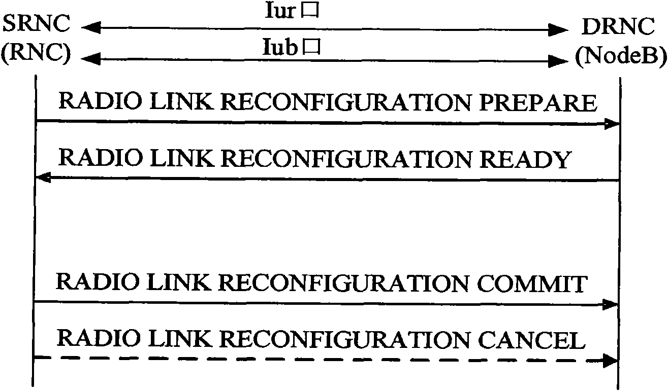
[0038] The failure signaling of the reconfiguration process is realized by extending the radio link failure indication message RADIO LINKFAILURE INDICATION, and the reason value of "error while waiting for reconfiguration submission" is added to the information element IE of the failure reason of the message, as shown in Table 1; the failure reason is based on Invented a new reason indicator value, used for receiving the synchronous radio link reconfiguration request side network element in the process of waiting for the radio link reconfiguration signaling (RADIO LINK RECONFIGURATION COMMIT, or RADIO LINK RECONFIGURATION CANCEL), if an internal error occurs or a failure, or when a timeout occurs, instruct the corresponding network element on the other side to cancel the reconfiguration.
[0039] The modifications involving the Iub port 25.433 protocol message / Iur port 25.423 protocol message are shown in Table 1, where bold italics, underlined parts, and blackened fonts are ne...
Embodiment 2
[0055] The reconfiguration process failure signaling is implemented by adding a new reconfiguration failure notification message WAITRECONFIG COMMIT FAIL NOTIFY. As shown in Table 2, the side network element used to receive the synchronous wireless link reconfiguration request waits for the wireless link reconfiguration request. In the process of signaling (RADIO LINK RECONFIGURATION COMMIT or RADIO LINK RECONFIGURATION CANCEL), if an internal error or failure occurs, or a waiting timeout occurs, instruct the corresponding network element on the other side to cancel the reconfiguration process. The bold italics, underlined parts and bold fonts in Table 2 are new parts.
[0056] Table 2 Add a new reconfiguration failure notification message
[0057]
[0058] like Figure 4 Shown, represent the method flow that DRNC and SRNC carry out synchronous reconfiguration through Iur mouth, comprise the following steps:
[0059] Step 1: SRNC sends a synchronous radio link reconfigura...
PUM
 Abstract
Description
Claims
Application Information