Pneumatic fixture

A pneumatic tooling and pneumatic clamping technology, applied in the field of machining, can solve the problems of clamping multiple workpieces, lengthening the loosening time, manual operation for clamping and loosening, and high labor intensity, and achieves compact structure, tooling The effect of simplifying the structure and reducing labor intensity

Inactive Publication Date: 2010-07-28
天津市中马骏腾精密机械制造有限公司
View PDF3 Cites 5 Cited by
  • Summary
  • Abstract
  • Description
  • Claims
  • Application Information

AI Technical Summary

Problems solved by technology

However, the structure of fixtures and fixtures used in existing machining centers is usually relatively simple, and has the following disadvantages in the process of use: For fixtures with a single piece of clamping, only one part can be processed once the tool is changed, and the efficiency is low, and the clamping of the workpiece Tightening and loosening are manual operations; for tooling with multiple workpieces, multiple parts can be processed by changing the tool once, but the time for clamping and loosening of multiple workpieces is also lengthened, the efficiency is low, and the labor intensity is high

Method used


Image

  • Pneumatic fixture
  • Pneumatic fixture
  • Pneumatic fixture

Examples


Embodiment Construction

[0022] The present invention will be further described in detail below through specific embodiments in conjunction with the accompanying drawings.

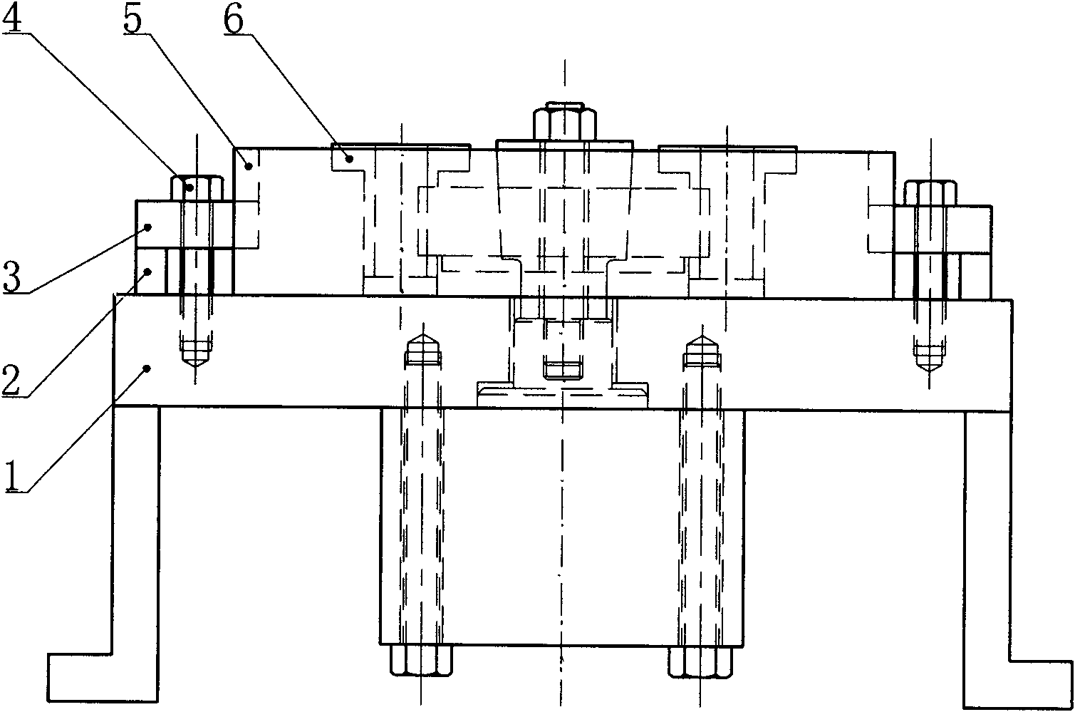
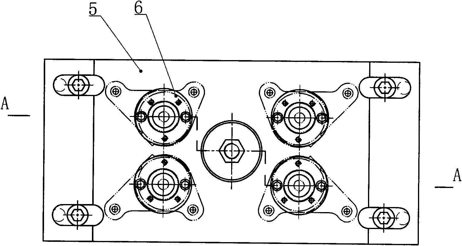
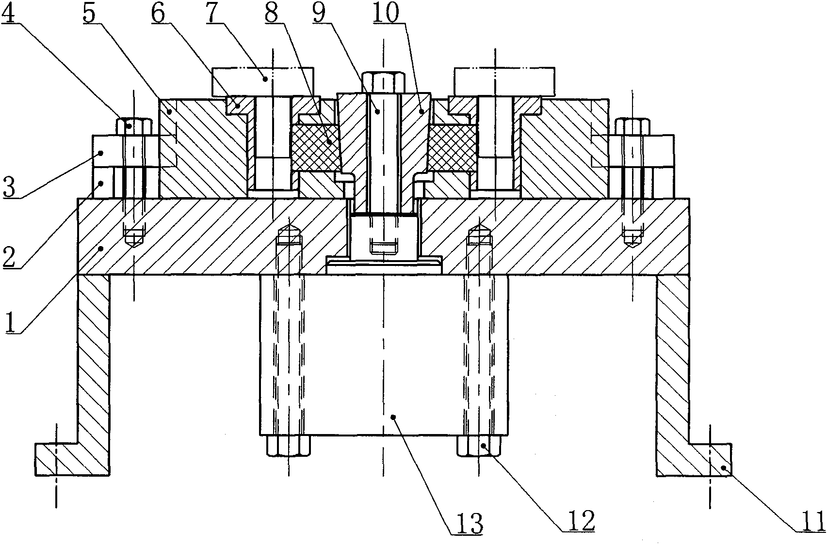
[0023] A pneumatic tooling is composed of a bottom plate 1 , legs 11 , a body 5 , a positioning sleeve 6 , a pneumatic clamping mechanism and a cylinder 13 . The outriggers are fixed on the lower part of the bottom plate. The main body is horizontally fixed on the upper surface of the bottom plate through the surrounding pressure plate 3, pads 2 and bolts 4. The cylinder is fixedly installed by bolts 12 at the bottom of the base plate. A pneumatic clamping mechanism is installed in the middle of the body, and 2-6 positioning sleeves are embedded on the body of the outer periphery of the pneumatic clamping mechanism, and four positioning sleeves are shown in this embodiment. The pneumatic clamping mechanism consists of a tapered sleeve 10, a wedge block 8 and a return spring 14. The tapered sleeve is installed vertically upside ...


PUM


Abstract

The invention relates to a pneumatic fixture, which consists of support legs, a base plate, a main body, positioning sleeves, a pneumatic fastening device and an air cylinder, wherein the support legs are fixedly arranged under the base plate; the main body is horizontally and fixedly arranged on the upper surface of the base plate; the middle part of the main body is provided with the pneumatic fastening device; the air cylinder is fixedly arranged under the base plate; the main body on the periphery of the pneumatic fastening device is inlaid with a group of positioning sleeve; the pneumatic fastening device consists of a cone-shaped sleeve, wedges and return springs, wherein the cone-shaped sleeve is movably arranged on the middle part of the base plate in a longitudinally inversed way, and is coaxially fixed with an air cylinder push rod; the wedge is inlaid between the cone-shaped sleeve and each positioning sleeve, the inclined plane of the wedge is in sliding fit with the cone-shaped sleeve, and the right angle face of the wedge is inlaid in the radial slot formed by each positioning sleeve; one end on which each wedge is inlaid into the positioning sleeve is machined with a radial blind hole; and the blind hole is provided with the return spring. The invention is applicable to the positioning and fastening of the part with more working procedures, higher precision and larger batch, and has the advantages of simple operation, high efficiency and stable and reliable running.

Description

technical field [0001] The invention belongs to the field of machining, in particular to a pneumatic tooling for a machining center. Background technique [0002] Machining centers are high-efficiency automatic machine tools suitable for processing complex-shaped workpieces composed of mechanical equipment and numerical control systems. The machining center has the function of automatic tool change. After the workpiece is clamped once, it can carry out centralized processing of various processes such as milling, drilling, boring, reaming and tapping. However, the structure of fixtures and fixtures used in existing machining centers is usually relatively simple, and has the following disadvantages in the process of use: For fixtures with a single piece of clamping, only one part can be processed once the tool is changed, and the efficiency is low, and the clamping of the workpiece Tightening and loosening are manual operations; for tooling that clamps multiple workpieces, mu...

Claims


Application Information

Patent Timeline
Patent Type & Authority Applications(China)
IPC IPC(8): B23Q3/06
Inventor 杜辰张钧沈连洪于建生
Owner 天津市中马骏腾精密机械制造有限公司
Why Eureka
Try Eureka