Optical member and display device
A technology for optical components and display devices, applied in optical components, optics, lighting devices, etc., can solve the problems of deterioration of backlight brightness and chromaticity, and reduction of phosphor color conversion efficiency, and achieves suppression of light loss and suppression of brightness reduction. , reduce the effect of light reflection
- Summary
- Abstract
- Description
- Claims
- Application Information
AI Technical Summary
Problems solved by technology
Method used
Image

Examples
no. 1 example
[0027] (1) First embodiment: Example in which a phosphor layer is directly provided on the light exit surface of a diffuser plate
[0028] (2) Modification 1: An example in which a phosphor layer is directly provided on the light incident surface of a diffuser plate
[0029] (3) Modification 2: An example in which a phosphor layer is directly provided on the light exit surface of a light guide plate
[0030] (4) Modification 3: Example in which a phosphor layer is directly provided on the bottom of the light guide plate
[0031] (5) Modification 4: An example of directly providing a phosphor layer on the light incident surface (side surface) of the light guide plate
no. 2 example
[0032] (6) Second embodiment: Example of adhering a phosphor plate to the light exit surface of a diffuser plate
[0033] (7) Modification 5: Example of adhering a phosphor plate to the light incident surface of a diffuser plate
[0034] (8) Modification 6: Example of adhering a phosphor plate to the light exit surface of a light guide plate
[0035] first embodiment
[0036] 1. Structure of the display device 1
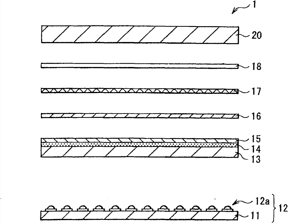
[0037] figure 1 The cross-sectional configuration of the display device 1 according to the first embodiment of the present invention is briefly shown. For example, the display device 1 is a liquid crystal display or the like, and has a display panel 20 and a light source 12 as a backlight for illuminating the display panel 20 . Between the display panel 20 and the light source 12, the diffuser plate 13 (base member), the phosphor layer 14, the protective layer 15, the diffuser film 16, the lens film 17, and the reflective polarizing film 18 are stacked in order f...
example 1
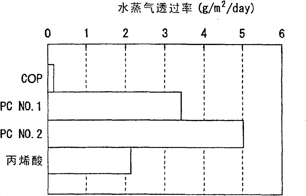
[0055] After that, as an example (Example 1) of the first embodiment described above, an experiment of degradation in phosphor layer 14 was conducted. Specifically, using a blue light-emitting diode and a diffusion plate 13 on which the phosphor layer 14 is not directly formed, the luminance efficiency was measured with respect to the water vapor transmission rate (g / m 2 / day) changes. Figure 4 The results are shown graphically. Relative values in the case where a phosphor for red conversion is used as the phosphor layer 14, the initial luminous efficiency is set to 1, and the phosphor layer stays for 500 hours in an environment of 85° C. and 90% RH are illustrated, Among them, phosphors used for red conversion generally suffer from greater degradation in high temperature and high humidity environments. From Figure 4 It can be recognized that the higher the water vapor transmission rate in the diffuser plate 13 , that is, the lower the water vapor barrier property, the ...
PUM
| Property | Measurement | Unit |
|---|---|---|
| thickness | aaaaa | aaaaa |
| thickness | aaaaa | aaaaa |
Abstract
Description
Claims
Application Information
 - R&D
- Intellectual Property
- Life Sciences
- Materials
- Tech Scout
- Unparalleled Data Quality
- Higher Quality Content
- 60% Fewer Hallucinations
Browse by: Latest US Patents, China's latest patents, Technical Efficacy Thesaurus, Application Domain, Technology Topic, Popular Technical Reports.
© 2025 PatSnap. All rights reserved.Legal|Privacy policy|Modern Slavery Act Transparency Statement|Sitemap|About US| Contact US: help@patsnap.com