
Refrigerant distributor for heat exchanger and heat exchanger

一种制冷剂分配器、热交换器的技术,应用在热交换设备、制冷和液化、蒸发器/冷凝器等方向,能够解决分层现象,由于重力作用,液态制冷剂在下方,气态制冷剂在上方等问题,达到减轻分层现象、混合均匀的效果

Active Publication Date: 2010-07-28
SANHUA(HANGZHOU) MICRO CHANNEL HEAT EXCHANGER CO LTD
View PDF0 Cites 15 Cited by
  • Summary
  • Abstract
  • Description
  • Claims
  • Application Information

AI Technical Summary

Problems solved by technology

However, there are still some problems with this kind of distributor. When the refrigerant flows in the distribution pipe, stratification will also occur. Due to the effect of gravity, the liquid refrigerant is at the bottom and the gaseous refrigerant is at the top.

Method used


Image

  • Refrigerant distributor for heat exchanger and heat exchanger
  • Refrigerant distributor for heat exchanger and heat exchanger
  • Refrigerant distributor for heat exchanger and heat exchanger

Examples


Embodiment 1

[0029] image 3 is a schematic front view of the refrigerant distributor according to the first embodiment of the present invention. Figure 4 yes image 3 A schematic top view of the refrigerant distributor shown. Figure 5 yes image 3 A perspective view of the refrigerant distributor shown. Such as Figure 3-5 As shown in , the distributor 1 comprises a round tube 9 . The circular tube 9 includes a plurality of outlets 8 for refrigerant outflow and inlets 7 for refrigerant inflow.

[0030] The diameter of the circular tube 9 shrinks to a predetermined diameter at regular intervals in the length direction of the circular tube 9 to form a necking section 6 as an example of a part with a reduced cross-sectional area, that is, D2 Figure 3-4 The right side of the middle enters the distributor 1, and every time it passes through a necking section 6, the refrigerant is sprayed once, so that the two-phase refrigerant is mixed evenly, a part of the refrigerant is sprayed out th...

Embodiment 2

[0037] A refrigerant distributor according to a second embodiment of the present invention will be described below. Image 6 is a schematic perspective view of a refrigerant distributor according to a second embodiment of the present invention. Figure 7 yes Image 6 Schematic front view of the refrigerant distributor shown. Figure 8 yes Image 6 A schematic top view of the refrigerant distributor shown. Such as Figure 6-8 As shown in , the distributor 1 comprises a round tube 9 . The circular tube 9 comprises a plurality of outlets 8 for the outflow of refrigerant. The difference from the first embodiment is that the flattened section 6', which is an example of a part with a reduced cross-sectional area, is different from the necked section 6 in the above-mentioned first embodiment. This flattened section 6' is convenient to process, and can be made In the shape of a flattened duckbill, such as Figure 6-8 shown in .

[0038] The distributor of the present invention...


PUM


Abstract

The invention provides a refrigerant distributor for a heat exchanger, which comprises a pipe used for distributing a refrigerant. The pipe is provided with a channel which is arranged in the pipe and is used for the refrigerant to flow. The channel is provided with at least one part, the sectional area of which is reduced. As the refrigerant distributor adopts the above structure, the layering of the refrigerant in the distribution pipe is reduced and the distribution of the refrigerant is uniform.

Description

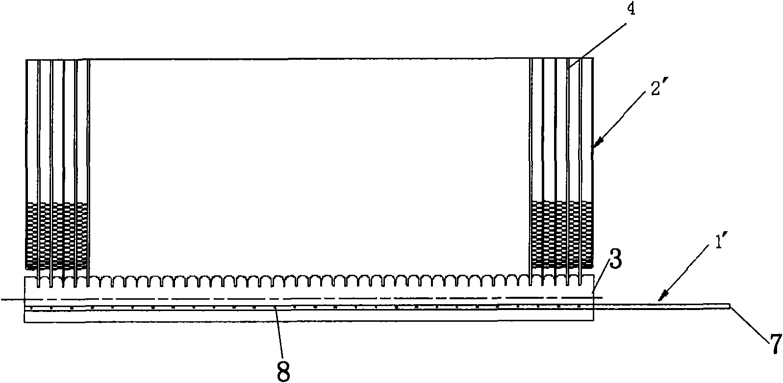
technical field [0001] The present invention relates to a refrigerant distributor for a heat exchanger and a heat exchanger with the refrigerant distributor. Background technique [0002] Such as Figure 1-2 As shown in , generally a microchannel heat exchanger 2' includes a refrigerant distributor 1' disposed at its end, and the refrigerant distributor 1' includes a tube 9'. The micro-channel heat exchanger also includes: a header 3 (another header opposite to the header 3 is omitted in the figure), the tube is arranged inside the header 3, and a plurality of outlets 8 are opened on the tube. The multi-circuit microchannel heat exchanger has a similar structure, except that multiple distributor tubes are arranged inside the header. [0003] If there is a two-phase refrigerant present, a two-phase refrigerant distribution problem will be encountered. To solve the refrigerant distribution problem, a distributor has been proposed such as figure 2 shown. The distributor 1'...

Claims


Application Information

Patent Timeline
Patent Type & Authority Applications(China)
IPC IPC(8): F28F9/22F28D1/00
CPCF25B39/028F28F9/0273
Inventor 刘华钊黄宁杰
Owner SANHUA(HANGZHOU) MICRO CHANNEL HEAT EXCHANGER CO LTD
Learn More