Device for measuring apparent viscosity of liquefied sand and method therefor

A technology for apparent viscosity and measuring devices, applied in measuring devices, flow characteristics, instruments, etc., can solve the problems of high apparent viscosity, beyond the measurement range of conventional viscometers, and inability to effectively measure apparent viscosity, so as to improve the test efficiency Effect

Inactive Publication Date: 2010-07-28
HOHAI UNIV
View PDF0 Cites 18 Cited by
  • Summary
  • Abstract
  • Description
  • Claims
  • Application Information

AI Technical Summary

Problems solved by technology

However, none of the above-mentioned viscosity measurement methods can effectively measure the apparent viscosity of saturated sandy soil after liquefaction due to:
[0004] (1) The falling ball viscometer requires the fluid to remain in a static state, while the liquefaction of saturated sand is produced under the action of vibration load, and the liquefied sand is in a state of motion, so the traditional falling ball viscometer is not suitable for the liquefaction state of saturated sand Apparent viscosity measurement under
[0005] (2) The capillary viscometer needs to use a slender glass tube, and the rotational viscometer requires the fluid to shear and flow in the slit, and the sand is a material with a certain particle size, which cannot flow smoothly in the slender glass tube or slit , so the apparent viscosity of liquefied sand is not suitable for measuring with capillary viscometer and rotational viscometer
[0006] (3) It has been proved by experiments that the apparent viscosity of saturated sand after liquefaction is very high, beyond the measurement range of conventional viscometers
[0007] (4) The rate of flow deformation after saturated sand liquefaction is low, while the rate of fluid movement is relatively high when measured by a conventional viscometer, which cannot reasonably reflect the characteristics of flow deformation of saturated sand after liquefaction

Method used


Image

  • Device for measuring apparent viscosity of liquefied sand and method therefor
  • Device for measuring apparent viscosity of liquefied sand and method therefor
  • Device for measuring apparent viscosity of liquefied sand and method therefor

Examples


Embodiment Construction

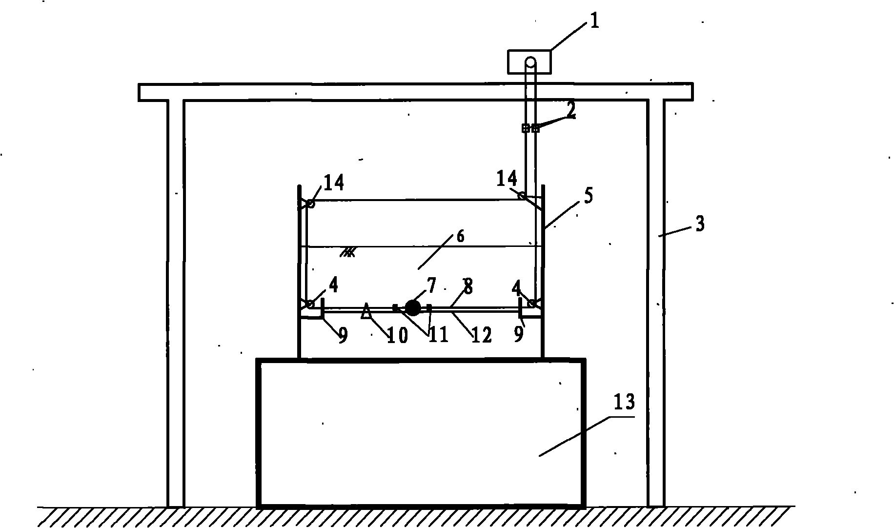
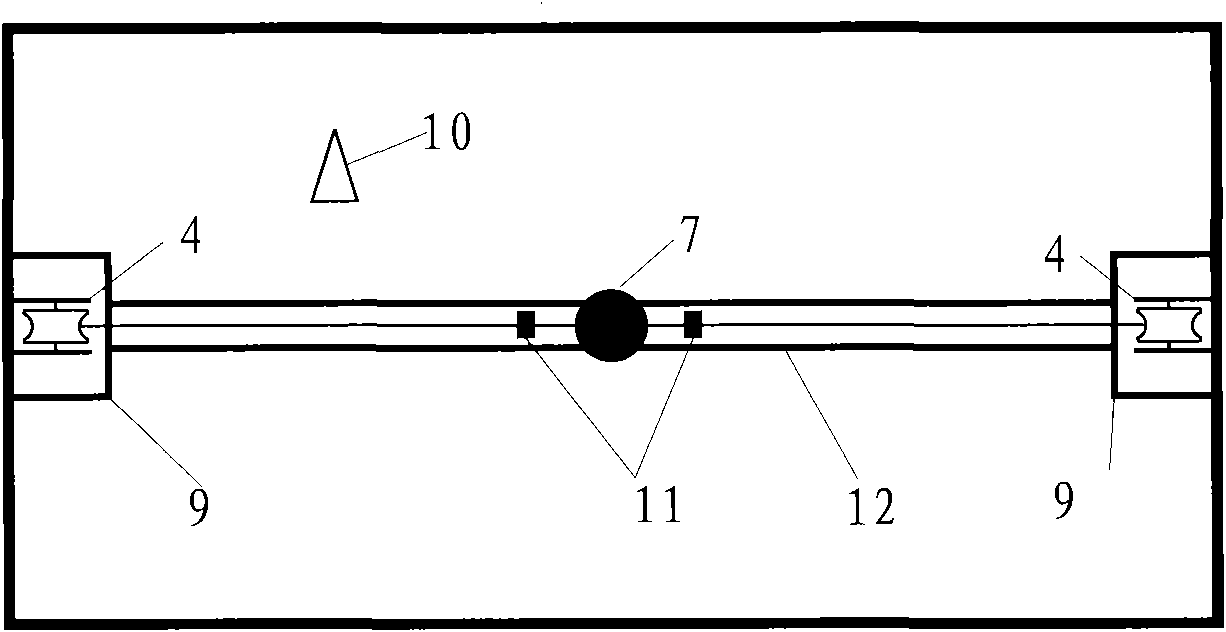
[0040] Such as figure 1 , figure 2 As shown, a device for measuring the apparent viscosity of saturated sandy soil after liquefaction includes a vibrating table 13 and a model box 5 fixed on the vibrating table 13, and also includes a low-speed adjustable motor 1, a dynamic displacement sensor 2, a fixed pulley 4, a steel Ball 7, wire rope 8, track support 9, dynamic hole pressure sensor 10, dynamic tension sensor 11, track 12 and fixed pulley 14. The excitation direction of the vibrating table 13 is perpendicular to the direction of the track 12 .

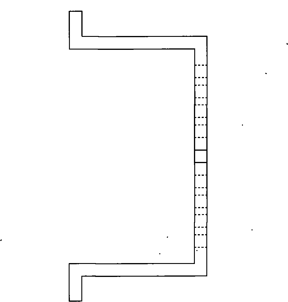
[0041] The track 12 is formed by two parallel smooth steel bars with a diameter of 5mm horizontally arranged in the model box, and can be fixed by two symmetrical track supports 9 . A kind of fixing method is to go out screw thread at both ends of the steel bar, pass through the round hole or groove in the track support 9, and fix with nuts. A group of holes with different distances can be set on the track support 9 to fix and...


PUM


Abstract

The invention relates to a device for measuring apparent viscosity of liquefied sand and a method therefor. The device comprises a vibration table and a model box, wherein a horizontal track is arranged in the model box; a rigid ball is placed on the track; both ends of the rigid ball are respectively connected with dynamic tension sensors which are pulled by traction ropes; the traction ropes are led out of the model box through a fixed pulley set and connected with two dynamic displacement sensors and then connected on a reversible regulating motor; and a dynamic pore pressure sensor is arranged at the equal height with the rigid ball in the model box. The saturated sand in the model box can be in the liquefaction state through the vibration table, the motor drives the rigid ball to do horizontal movement on the track, the speed and resistance of the rigid ball are measured, and the apparent viscosity of the liquefied sand is calculated. The invention solves the technical problems of apparent viscosity measurement of the liquefied sand, can perform parallel test in the same test and has the advantages of high test efficiency and small boundary effect.

Description

technical field [0001] The invention relates to a viscosity measuring device and method, in particular to a measuring device and method for the apparent viscosity of liquefied sandy soil. Background technique [0002] Liquefaction characteristics of sandy soil is a research hotspot in soil dynamics. The total stress of saturated sand is composed of effective stress and pore water pressure. Generally, due to the existence of effective stress, the pore water pressure of sand is less than the total stress. However, under dynamic loads such as earthquakes and explosions, the pore water pressure in the saturated sand will continue to rise. When the pore water pressure increases to equal the total stress, the effective stress in the sand is equal to zero, and the sand skeleton is lost. When the force is exerted, the sand particles are "suspended" in the water. At this time, the sand becomes a fluid-like substance and loses its shear strength and bearing capacity. This is the liqu...

Claims


Application Information

Patent Timeline
Patent Type & Authority Applications(China)
IPC IPC(8): G01N11/10
Inventor 陈育民丁选明刘汉龙杨贵于陶沙小兵
Owner HOHAI UNIV
Why Eureka
Try Eureka