
Heat dissipation fault warning method of LED lamp and heat dissipating device

A technology of LED lamps and heat dissipation devices, which is applied to the cooling/heating devices of lighting devices, lighting devices, components of lighting devices, etc., and can solve the problem that the life of LED lights is reduced to 1,000 to 2,000 hours, and the problem of heat dissipation cannot be solved. Problems such as pollution and heat dissipation, to achieve the effect of protecting LED lights, saving development costs, and shortening lifespan

Inactive Publication Date: 2012-12-26
陈鸿 +1
View PDF0 Cites 0 Cited by
  • Summary
  • Abstract
  • Description
  • Claims
  • Application Information

AI Technical Summary

Problems solved by technology

But no matter how the efficiency is improved, there is a considerable problem, that is, the problem of heat dissipation has not been solved, so that the production of a perfect energy-saving lighting product has stagnated.
LED lamps are used normally and have a lifespan of 80,000 to 100,000 hours. However, because their radiators are exposed to the air for a long time, the heatsink itself will dissipate heat due to air pollution (exhaust gas and dust from automobiles or factories, etc.) Gradually, problems will arise, and the temperature will rise accordingly, reaching the light decay temperature point of the LED itself (the temperature point at which the life is broken), which will reduce the life of the LED lamp to 1,000 to 2,000 hours.

Method used


Image

  • Heat dissipation fault warning method of LED lamp and heat dissipating device
  • Heat dissipation fault warning method of LED lamp and heat dissipating device
  • Heat dissipation fault warning method of LED lamp and heat dissipating device

Examples


Embodiment Construction

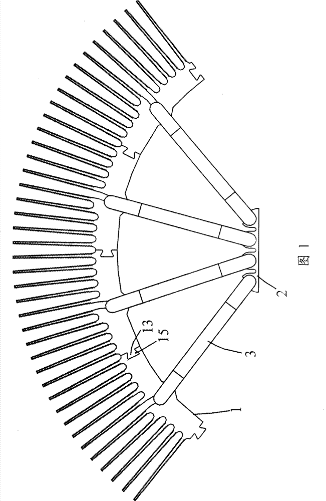
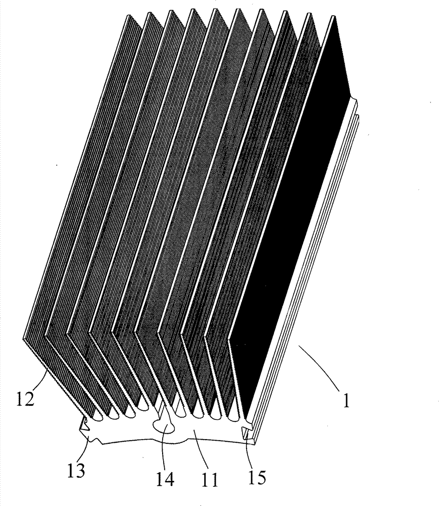
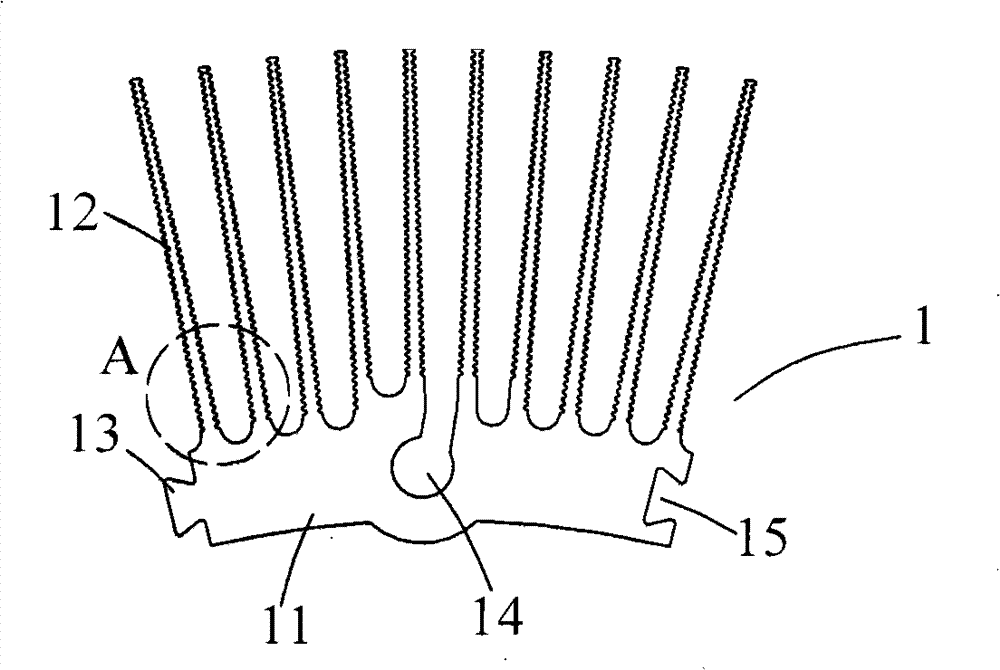
[0036] refer to Figure 1-5, The LED lamp cooling device with fault warning and protection functions includes: a radiator 1, a heat conducting element 2, four superconducting heat pipes 3, a temperature sensor and a control circuit. The radiator 1 is composed of four radiator components 1 , and two adjacent radiator components 1 are connected as a whole through connecting protrusions 13 and corresponding connecting grooves 15 . The heat conduction element 2 is placed on the inner arc surface side of the radiator component, and a plurality of heat pipe installation holes 21 are arranged on the heat conduction element 2 . One end of the superconducting heat pipe 3 is inserted into the heat pipe mounting hole 21 on the heat conducting element 2 and welded, and the other end is inserted into the heat pipe mounting hole 14 on the radiator component 1 and welded. During installation, the temperature sensor is installed on the substrate of the LED lamp module.

[0037] refer to F...


PUM


Abstract

The invention relates to a heat dissipation fault warning method of an LED lamp. The substrate of an LED lamp module is provided with a heat dissipating device; the temperature of the substrate of the LED lamp module is detected by using a temperature sensor; when the temperature of the substrate is higher than the maximum temperature, a control circuit cuts off the power supply of an LED lamp; when the temperature of the substrate drops to be lower than the maximum temperature, the control circuit switches on the power supply of the LED lamp; when the temperature of the substrate raises again to be higher than the maximum temperature, the control circuit cuts off the power supply of the LED lamp again; by repeating in such a manner, the discontinuous lighting of the LED lamp is utilized to warn that the LED lamp generates a heat dissipation fault; street lamp managers know that the heat dissipating device of the LED lamp generates fault when finding the discontinuous lighting of the LED lamp, and the maximum temperature is smaller than the light attenuation temperature of the LED lamp. The method can enable the LED lamp with the heat dissipation fault to be very easily found by the street lamp managers, thereby, the LED lamp is maintained in time. Meanwhile, the temperature of the LED lamp can be controlled to be lower than the light attenuation temperature, thereby achieving the goal of protecting the LED lamp.

Description

technical field [0001] The invention relates to a heat dissipation failure warning method of an LED lamp for lighting, in particular to a heat dissipation failure warning method of an LED light and a heat dissipation device with failure warning and protection functions. Background technique [0002] In response to the requirements of the environmental protection era, the requirements for energy-saving and emission-reducing products are getting higher and higher, and the related lighting equipment also has white light due to the invention of LED blue light, and thus becomes a part of lighting, the so-called solid-state lighting (SSL) , The US Department of Energy has the SSL Association. The conversion of the power and luminous flux of a fluorescent lamp is about 15W=490lm~560lm, 20W=700lm~800lm, 30W=1160lm~1400lm, 40W=1700lm~1920lm. The conversion of 220V incandescent bulb power and luminous flux is roughly 10W-65lm, 15W-101lm, 25W-198lm, 40W-340lm, 60W-540lm, 100W-1050lm.....

Claims


Application Information

Patent Timeline
Patent Type & Authority Patents(China)
IPC IPC(8): F21V25/04F21V9/00F21Y101/02F21V23/00F21V29/51F21V29/77F21V29/89
Inventor 杨然森
Owner 陈鸿
Learn More