LED power supply with no-load and light-load protection output and capable of receiving phase-cut dimming stably

A LED power supply, phase-cut dimming technology, applied in the direction of light source, electric light source, lamp circuit layout, etc., can solve the problems of low power supply, low power supply efficiency, low dimming angle, etc., to solve the problem of hot swap protection, Good linearity of dimming control and the effect of high power design

Inactive Publication Date: 2010-07-28
李福南
View PDF1 Cites 22 Cited by
  • Summary
  • Abstract
  • Description
  • Claims
  • Application Information

AI Technical Summary

Problems solved by technology

But above-mentioned method all exists power supply is little, and power supply efficiency is low (efficiency is all below 80%), especially in the method for patent No. 200820213150.0, also added resistance dummy load on power supply, efficiency is just lower; Dimming There are obvious flickering phenomenon when the angle is low; there are many unsolvable problems when passing EMI and EMC
At the same time, because in the above circuit, when the constant current source is no-load, the output voltage is very high, and there is no design for LED no-load or light-load protection, and it is very easy to burn out the LED in the case of hot plugging.
Therefore, the above scheme is not easy to popularize and apply in LED dimming control

Method used


Image

  • LED power supply with no-load and light-load protection output and capable of receiving phase-cut dimming stably
  • LED power supply with no-load and light-load protection output and capable of receiving phase-cut dimming stably
  • LED power supply with no-load and light-load protection output and capable of receiving phase-cut dimming stably

Examples


Embodiment Construction

[0040] The present invention will be further described below in conjunction with the accompanying drawings and specific embodiments.

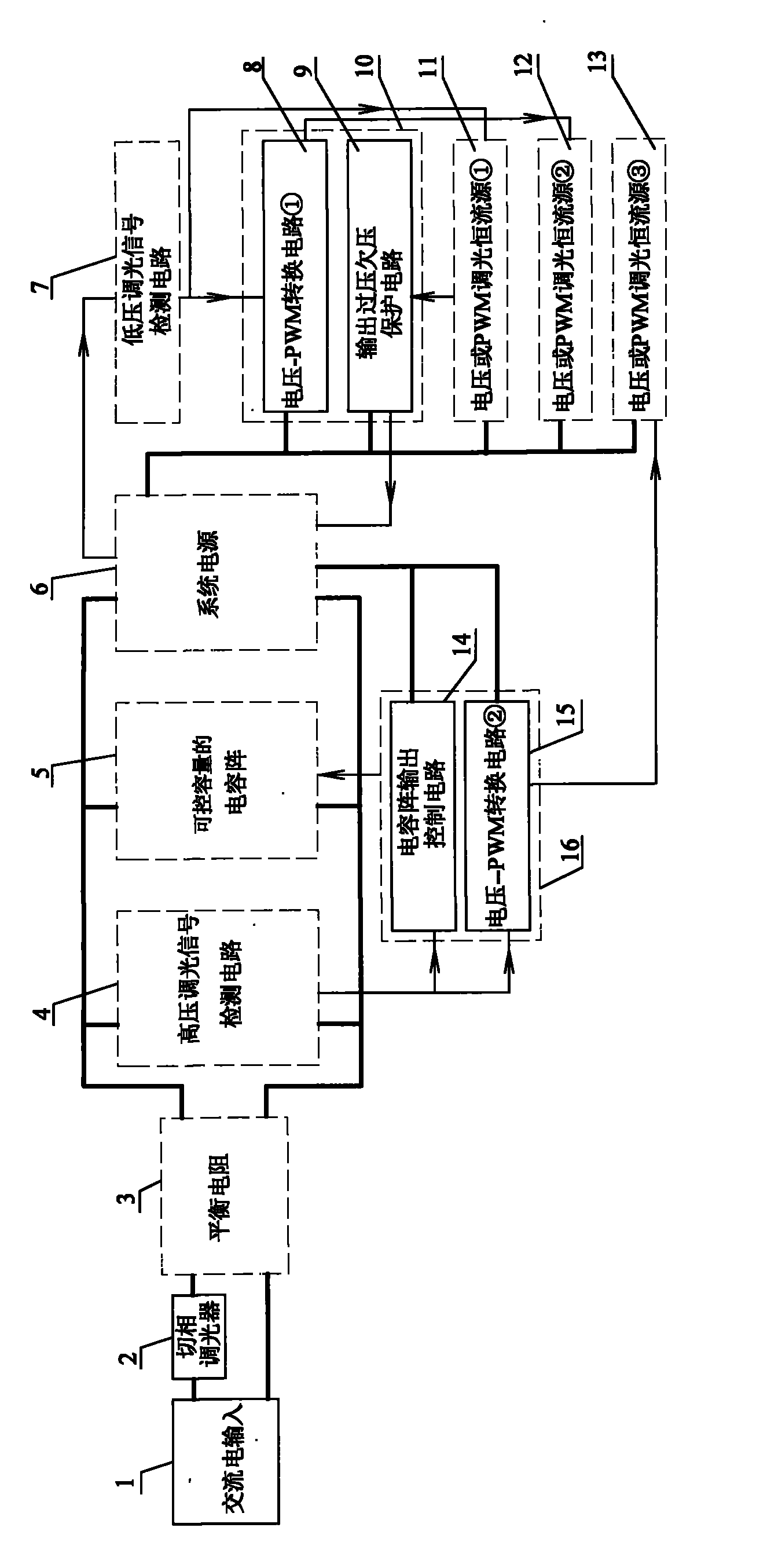
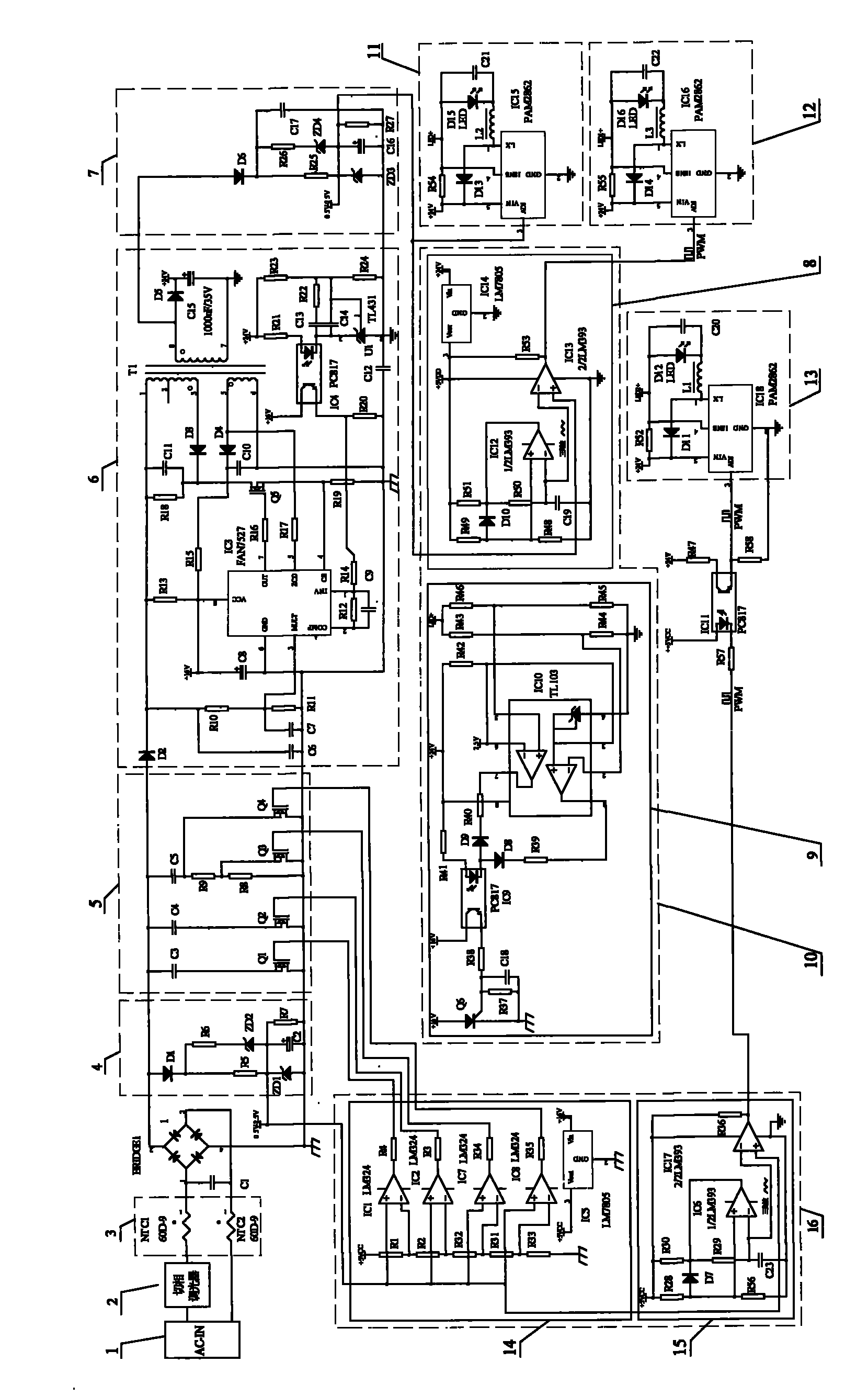
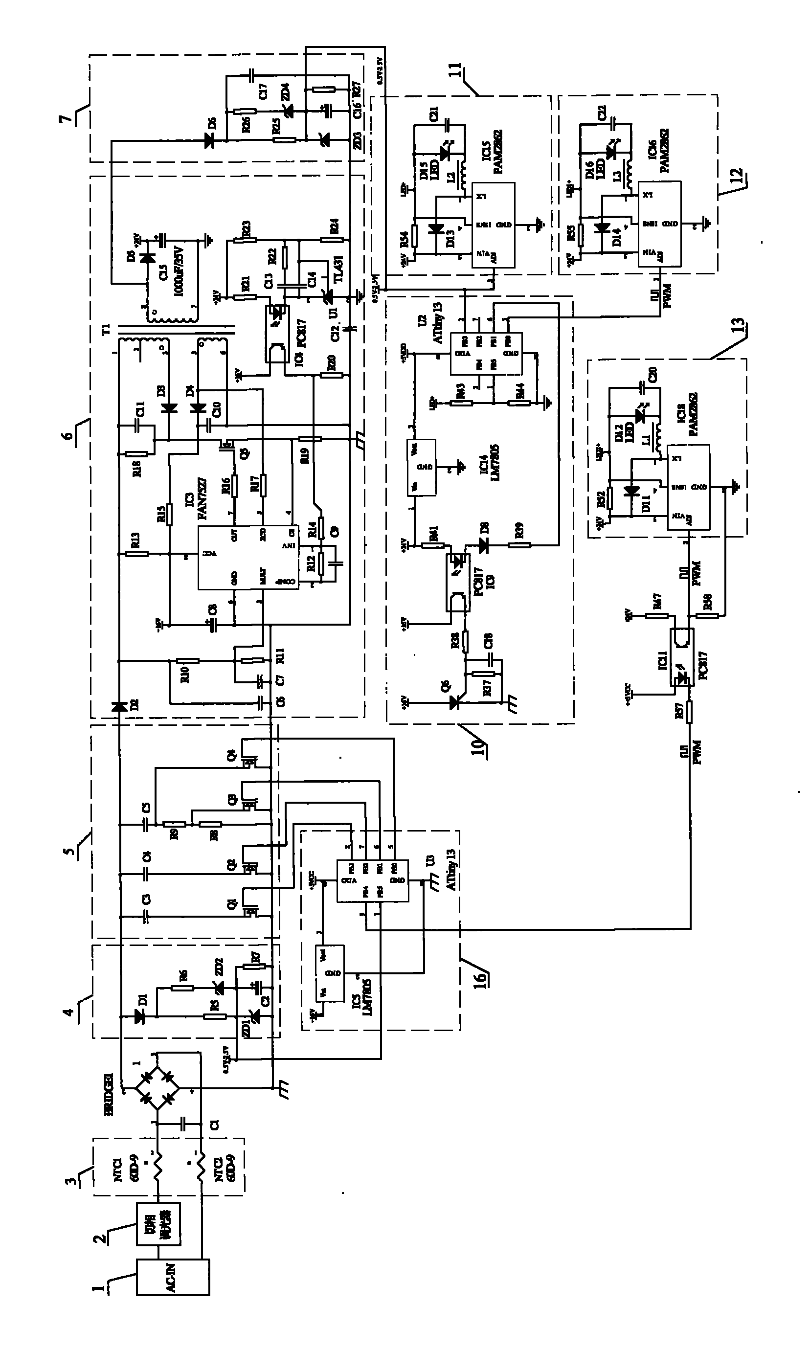
[0041] Such as figure 1 Shown is a schematic block diagram of the circuit of the present invention, which includes: a phase-cut dimmer (2), a balance resistor (3), a high-voltage dimming signal detection circuit (4), a capacitor array with controllable capacity (5), and a system power supply (6), low-voltage dimming signal detection circuit (7), voltage-PWM conversion circuit ① (8), output overvoltage and undervoltage protection circuit (9), voltage or PWM dimming constant current source ① (11), voltage or PWM dimming constant current source ② (12), voltage or PWM dimming constant current source ③ (13), capacitor array output control circuit (14), voltage-PWM conversion circuit ② (15);

[0042] in:

[0043] (1), the voltage--PWM conversion circuit 1. (8) and the output overvoltage and undervoltage protection circuit (9) can be combined to for...


PUM

PropertyMeasurementUnit
Resistanceaaaaaaaaaa

Abstract

The invention discloses an LED power supply with no-load and light-load protection output and capable of receiving phase-cut dimming stably, which comprises a balancing resistor, a high-voltage dimming signal detecting circuit, a capacitor array with controlled volume, a system power supply, a low-voltage dimming signal detecting circuit, a voltage-PWM conversion circuit, an output overvoltage and undervoltage protection circuit, a voltage or PMW dimming constant-current source, and a capacitor array output control circuit, wherein the capacitor array with the controlled volume is controlled by the capacitor array output control circuit to match the balancing resistor consisting of NTC thermistors, so that the power of the power supply forms a certain direct proportion relation with filtering capacitance; a phase-cut dimmer is in a good phase-cut state, and a dimming signal is generated by the dimming signal detecting circuits to control an LED constant-current source so as to realize the LED dimming of the LED power supply; and the overvoltage and undervoltage protection circuit is set at the output of a constant-current power supply, so that LED hot plug and no-load and light-load protection are realized. Therefore, the LED power supply has great application prospects in the aspect of LED dimming.

Description

Technical field [0001] The invention relates to a phase-cut dimming power supply, and more specifically, to an LED power supply with no-load and light-load protection and stable phase-cut dimming. Background technique [0002] At present, the phase-cut dimming is generally accepted by high-power, high-thermal-resistance incandescent lamps or halogen lamps powered by AC. It is a kind of luminous body load (such as an incandescent bulb) that is directly connected in series to a phase-cut dimmer without circuit control. Phase-cut dimming on the output, when dimming, because of their high power and high thermal resistance, they have good dimming linearity, can achieve 0-100% dimming, and have no flicker, so they have been widely used. However, with the increasing development of science and technology, a kind of low power consumption, long life and energy-saving LED lighting has appeared, and has been widely applied in various fields. However, since the LED is a non-linear semic...

Claims


Application Information

Patent Timeline
IPC IPC(8): H05B37/02
Inventor 李福南
Owner 李福南
Why Eureka
Try Eureka