Charging circuit, and battery pack and charging system equipped with same

A charging circuit, battery connection technology, applied in battery pack components, battery overcharge protection, battery disconnect circuit, etc., can solve problems such as charging interruption and failure to detect faults

Inactive Publication Date: 2010-07-28
PANASONIC CORP
View PDF1 Cites 19 Cited by
  • Summary
  • Abstract
  • Description
  • Claims
  • Application Information

AI Technical Summary

Problems solved by technology

[0005] However, in the technology described in Patent Document 1, since the failure diagnosis of the switching element is performed before the start of charging and when any functional operation other than the charging operation is not performed after the charging is completed, there may be problems when charging When a switching element fails, the failure cannot be detected until charging is complete
In addition, if fault diagnosis is performed during charging, the technology described in Patent Document 1 must turn off the switching element of the constant current circuit in order to detect a fault, so there is a problem that charging is interrupted.

Method used


Image

  • Charging circuit, and battery pack and charging system equipped with same
  • Charging circuit, and battery pack and charging system equipped with same
  • Charging circuit, and battery pack and charging system equipped with same

Examples


Embodiment Construction

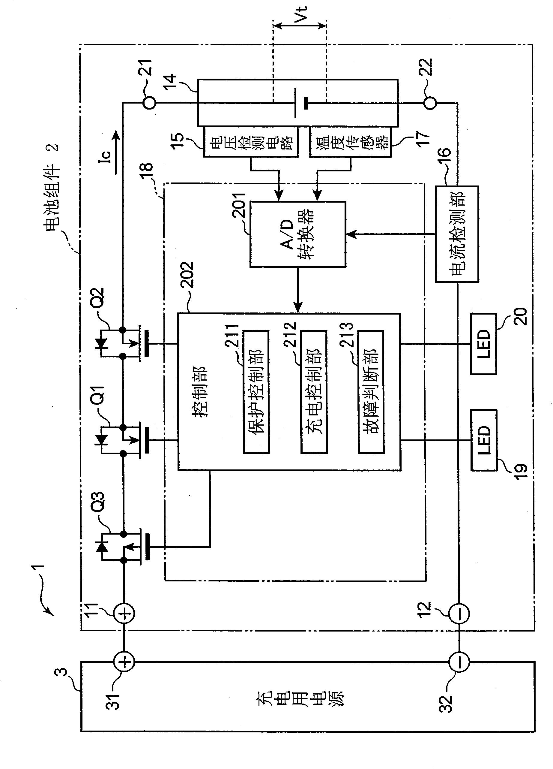
[0017] Embodiments according to the present invention will be described below with reference to the drawings. In addition, the structures attached|subjected to the same code|symbol in each figure represent the same structure, and the description is abbreviate|omitted. figure 1 It is a block diagram showing an example of a configuration of a battery pack including a charging circuit according to an embodiment of the present invention, and a charging system including the battery pack. figure 1 The shown charging system 1 includes a connected battery pack 2 and a charging power source 3 (power supply unit). In addition, this charging system 1 can also be used as an electronic equipment system that further includes a load device (not shown) powered by the battery pack 2 . In this case, although battery pack 2 is in figure 1 The battery pack 2 is charged by the charging power supply 3, but the battery pack 2 may also be installed in the load device and be charged by the load devi...


PUM


Abstract

A charging circuit is provided with a battery connecting terminal for connecting a secondary battery; an electric power connecting terminal for receiving an electric current to charge the secondary battery from an electric power source unit; first and second switching elements serially connected between the electric power connecting terminal and the battery connecting terminal to switch on or off the flow of the electric current from the electric power connecting terminal to the battery connecting terminal; an electric current detecting unit for detecting the flow of the electric current from the electric power connecting terminal to the battery connecting terminal; a charging control unit for supplying the battery connecting terminal with a pulse-like charging electric current by repeating a step for turning on the first and second switching elements, a step for turning on the first switching element while turning off the second switching element, and a step for turning off the first switching element while turning on the second switching element; and a fault judging unit for judging that at least one of the first and second switching elements is out of order in the case where the electric current detected by the electric current detecting unit is more than an electric current threshold value set for judging if there is the flow of an electric current to the battery connecting terminal during such a period that either one of the first and second switching elements is only turned on by the charging control unit.

Description

technical field [0001] The present invention relates to a charging circuit for charging a secondary battery, a battery pack including the charging circuit, and a charging system. Background technique [0002] Conventionally, there are electronic devices equipped with a charging circuit for charging a secondary battery. In such a charging circuit, in order to prevent overcharging of the secondary battery, switching elements are generally provided in the charging path. In this charging circuit, the switching element is turned on during charging, and the battery voltage or charging current is monitored. In addition, when the full charge of the secondary battery is detected from the battery voltage or charging current, the aforementioned switching element is set to a non-conductive state, and subsequent charging is stopped, thereby preventing deterioration and liquid leakage of the secondary battery caused by overcharging. , smoke, fire etc. [0003] On the other hand, if the...

Claims


Application Information

Patent Timeline
Patent Type & Authority Applications(China)
IPC IPC(8): H02J7/00H01M10/44H01M50/569
CPCY02E60/12H01M10/486H01M10/44H01M10/48H02J7/0093H02J7/0031H02J7/00711Y02E60/10H02J7/00302H02J7/00306H01M50/569
Inventor 谷口桂太郎
Owner PANASONIC CORP
Why Eureka
Try Eureka