High flow-rate medium pressure resin bed

A high flow rate, resin bed technology, applied in water/sewage treatment, water/sludge/sewage treatment, chemical instruments and methods, etc., can solve problems such as increased manufacturing costs, easy to pull out welded joints, and reduced space. Achieve the effect of reducing manufacturing cost and operating cost, reducing material cost and processing cost, and avoiding irreparable damage

Active Publication Date: 2010-08-04
CEEP CO LTD
View PDF1 Cites 4 Cited by
  • Summary
  • Abstract
  • Description
  • Claims
  • Application Information

AI Technical Summary

Problems solved by technology

The water distribution uniformity of the equipment with the main pipe structure is poor, which will stir the light filler resin layer in the container equipment, affecting the water quality of the treated water and the water production cycle of the running container. At the same time, due to the large amount of treated water, the diameter of the main pipe Thick, difficult to install, and high manufacturing cost; the overall porous plate structure with manholes has good water distribution uniformity. From the perspective of the overall stress of the porous plate, the stress concentration at the welding point between the porous plate and the cylinder, once the porous plate The plate is stressed, and the welding joint between the perforated plate and the cylinder is easily damaged, causing irreparable damage. Therefore, this structure has higher requirements for the impact force of the water inlet. It needs to be thickened, and the installation of the manhole on the perforated plate is difficult, otherwise, the manhole parts that can withstand medium pressure on the container equipment are required, the processing is complicated, and the manufacturing cost is high
[0004] In the current high-velocity and large-flow operating equipment, there is still unstable water flow caused by the wall effect. In the water inlet area of ​​the container equipment, under the action of the water inlet baffle, a water flow will be generated along the container. The cylinder wall flows into the lower part of the running bed and enters the water outlet area, which affects the quality of the treated water. This phenomenon will be more obvious when the water inlet pressure is higher.
[0005] In the condensate polishing treatment of the power station and the industrial condensate reuse advanced treatment system, the pressure of the water inlet area of ​​the operating container is generally 2.5-4.5MPa, the differential pressure is generally 0.1-0.25MPa, and the pressure of the water outlet area is generally 2.4-4.4 Between MPa, in a conventional operating container, the water outlet area generally needs to be lined with rubber or stainless steel for anticorrosion. When the water outlet area is lined with rubber, under the condition of a certain equipment height, since the rubber lining area of ​​the container needs a certain space, this must be The space in the operating area of ​​the equipment is reduced, which affects the processing capacity of the container equipment and the quality of the treated water. If the rubber lining space in the water outlet area is reduced, the rubber lining operation and the quality of the rubber lining will be affected. When the water outlet area is made of stainless steel, the water outlet area will bear The pressure is higher, and the stainless steel parts used must be thicker, which increases the manufacturing cost

Method used


Image

  • High flow-rate medium pressure resin bed
  • High flow-rate medium pressure resin bed
  • High flow-rate medium pressure resin bed

Examples


Embodiment Construction

[0018] The device of the present invention will be further described below in conjunction with the accompanying drawings.

[0019] A medium-pressure resin bed with a high flow rate, with a cylinder flow rate of 80-120m / h, a design pressure of PN1.6 to 5.0MPa, and a design temperature of 30°C to 85°C.

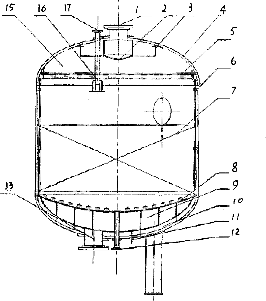
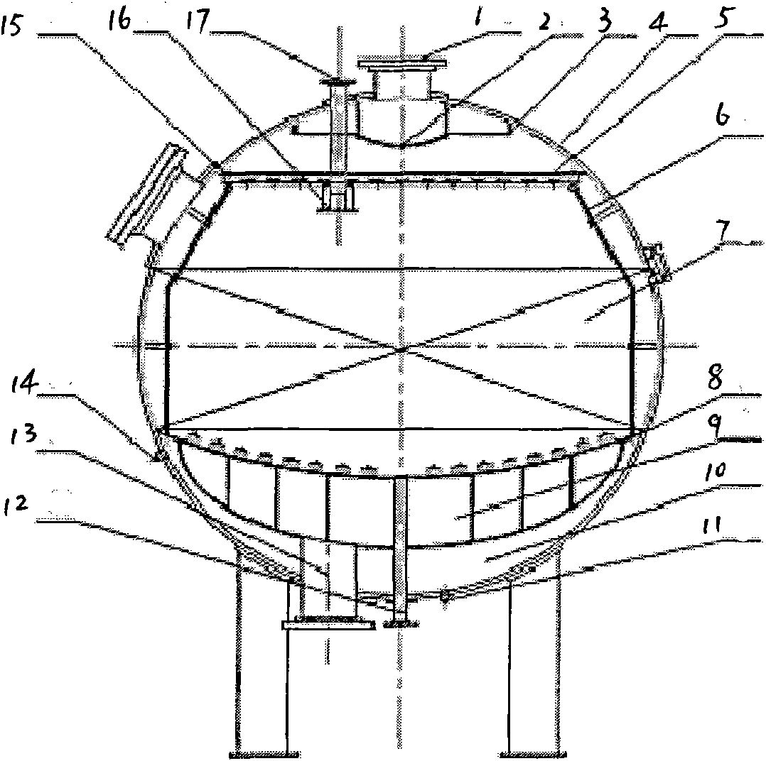
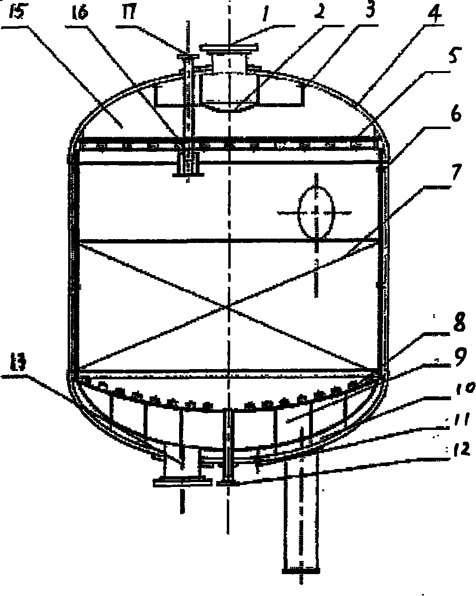
[0020] figure 1 Shown is a high flow rate medium pressure resin bed, its structure mainly includes water inlet 1, water baffle plate 2, splash guard 3, cylinder body 4, water inlet device 5, pressure balance pipe 6, resin layer 7, water outlet device 8. Water outlet area 9, pressure balance area 10, balance area drain port 11, resin outlet port 12, water outlet port 13, balance area exhaust port 14, water inlet device support ring 15, resin inlet baffle plate 16, resin inlet port 17 .

[0021] The barrel 4 of the high-flow medium-pressure resin bed can be spherical or cylindrical. For containers with the same wall thickness, the pressure resistance of the spherical container i...


PUM

PropertyMeasurementUnit
diameteraaaaaaaaaa

Abstract

The invention relates to a high flow-rate medium pressure resin bed comprising a water inlet (1), a water retaining plate (2), a splashing preventing ring (3), a cylinder (4), a water inlet device (5), a pressure balancing pipe, a resin layer, a water outlet device, a water outlet area (9), a pressure balancing area, pressure balancing area water draining outlet, a resin outlet, a water outlet, apressure balancing area air exhausting outlet (14), a water inlet device support ring and a resin inlet. The resin outlet is arranged on the lowest part of the water outlet device; the resin layer, the water outlet area (9) and the pressure balancing area are separated by the water outlet device; the water retaining plate (2) is arranged on the water inlet (1); the splashing preventing ring (3) is arranged outside the water retaining plate (2); the water inlet device support ring is directly welded on the cylinder (4); and the pressure balancing area water draining outlet and the pressure balancing area air exhausting outlet (14) are arranged in the pressure balancing area. When the high flow rate of the cylinder is 80-120 m / h, the high flow-rate medium pressure resin bed can evenly distribute and accumulate water in a large-diameter operating container. Adopting the flexibly-designed water distributing device with a reinforcing plate, the high flow-rate medium pressure resin bed can meet the requirement of processing water and reducing the manufacturing cost and the operating cost.

Description

technical field [0001] The present invention relates to a kind of water treatment equipment, especially medium-pressure resin bed equipment with high flow rate. Power station condensate polishing treatment and industrial condensate reuse advanced treatment system with a water treatment capacity of 250m3 / h~1500m3 / h. Background technique [0002] In the power station condensate polishing treatment and industrial condensate reuse advanced treatment system, due to the large amount of treated water required by the system and the high quality of the treated water, everyone is concerned about the water distribution uniformity of the operating equipment and the selection of excellent supporting equipment. Improve the effluent quality of the treatment system and extend the operating cycle of the system. At present, with the advancement of water treatment technology and the improvement of domestic processing technology and processing equipment, on the premise of satisfying the system...

Claims


Application Information

Patent Timeline
Patent Type & Authority Applications(China)
IPC IPC(8): C02F1/00
Inventor 袁劲梅南晓东
Owner CEEP CO LTD
Why Eureka
Try Eureka